Transmission and Distribution: Unit V: (a) Distribution Systems
High Voltage Direct Current Transmission
Principle - Advantages - Disadvantages - Types - Standard Rated Voltages
Questions : 1. With a neat schematic, explain the principle of HVDC system operation. 2. What are the advantages and disadvantages of HVDC system? 3. Explain the different types of HVDC links in detail.
High Voltage Direct
Current Transmission
In early days the transmission,
distribution and utilization of electrical energy was dominated by a.c. After
the introduction of large, high powered mercury are rectifiers, d.c. is also
considered for transmission of electrical energy economically.
1. Principle of HVDC Transmission System Operation
A typical HVDC transmission system is
shown in the Fig. 7.25.1. At sending end there is one rectifier unit whereas
one inverter unit at the receiving end. The two ends are interconnected by a dc
transmission line. The ac produced by generating stations after stepping up is
converted to dc by rectifier whereas the inverter converts dc to ac.
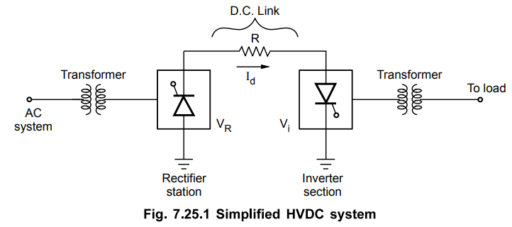
The converter makes use of thyristor for
controlled operation. Thus by varying the firing angle of the thyristor, the
d.c. output voltage magnitude is controlled. The firing angle is between 0° and
90° in rectifier while in inverter the firing angle is between 90° and 180°.
The converter and inverter station in HVDC uses three phase controlled bridge
converters.
From the Fig. 7.25.1 current Id
is given by,
Id = VR - Vi /
R
where VR
= D.C. output voltage at rectifier side
Vi = D.C. input voltage at
inverter side
The power transfer is given by,
Pd = Id . Vi =
(VR – Vi / R) Vi
2. Advantages of HVDC Transmission
1. These systems are economical for bulk
transmission of power for long distances as the cost of conductor reduces since
d.c. system requires only two conductors or even one if ground is used as
return. Similarly the cost of supporting towers and insulation is also reduced.
Also the transmission losses are reduced.
2. There are no stability problems with
d.c. system. Hence asynchronous operation of transmission link is possible.
3. The line length is not limitation as
there is no charging current in d.c. systems. Cables in d.c. system does not
suffer from high dielectric loss. The skin effect is also low in d.c. system.
4. Greater power transmission per
conductor is possible with d.c. system.
5. There are no serious problems of
voltage regulation as there is no reactance drop that exists in d.c. at steady
state.
6. The corona loss is low in d.c.
systems. The radio interference with HVDC is less.
7. The losses are less in transmission
with d.c.
8. The fault level increases with
interconnections of ac grids through ac lines whereas interconnection of a.c.
grids through d.c. links does not increase fault level to that extent.
9. With HVDC link there is easy
reversibility and controllability of power flow.
10. Shunt compensation is not required
in d.c. lines.
11. Intermediate substations are not
required with HVDC transmission.
12. During fault with HVDC system, the
grid control of the converter reduces the fault current significantly.
13. The transient stability of the power
system can be improved by making parallel connection of HVAC and HVDC lines.
3. Disadvantages of HVDC Transmission
1. The power transmission with HVDC is
not economical if length of transmission is less than 500 km as HVDC system
additionally requires converters, inverters and filters .
2. With multiterminal d.c. the circuit
breaking is difficult and expensive.
3. Considerable reactive power is
required by converter stations .
4. Harmonics are generated with d.c.
system hence Alteration is necessary
5. Overload capacity of HVDC converters
is low.
6. There should be local supply of
reactive power if required as HVDC will not transmit reactive power.
7. The maintenance of insulators in HVDC
system is more.
8. There are additional losses in
converter transformers and valves. These losses are continuos. Hence cooling
system must be effective to dissipate the heat.
4. Types of HVDC Systems (HVDC Links)
Depending on the arrangement of pole and
earth return, HVDC systems are classified in different types. The pole is
nothing but the path of direct current which has same polarity with respect to
earth.
Following are the different types of
HVDC systems.
1. Monopolar HVDC transmission system
Monopolar HVDC transmission system is
represented in the Fig. 7.25.2. This system has only one pole and the return
path is provided by permanent earth or sea. The pole generally has negative
polarity with respect to earth.
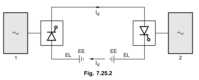
Full power and current is transmitted
through a line conductor with earth or sea as a return conductor. The earth
electrodes are designed for continuous full current operation. The sea or ground
return is permanent and of continuous rating.
2. Bipolar HVDC transmission system
This system has two poles, one positive
and one negative pole with respect to earth. During fault on one pole the
bipolar system is changed to monopolar mode. The system is represented in the
Fig. 7.25.3.
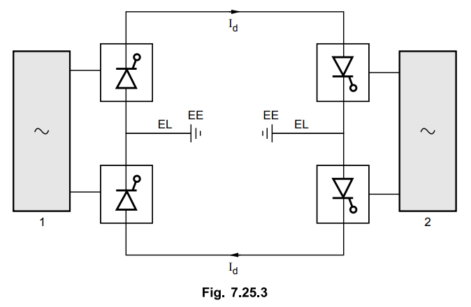
This system is more commonly used for
transmission of power over long distance. The mid points of convertors at each
terminal are earthed through electrode line and earth electrode. Power rating
of one pole is about half of bipoler power rating. The earth carries only small
out of balance current during normal operation.
The normal bipolar HVDC system consists
of two separate monopolar systems with a common earth. The two poles can
operate independently. Normally they are operated with equal currents and hence
ground carries no current.
3. Homopolar HVDC system
This system consists of two poles of
same polarity and the return is through permanent earth. It is shown in the
Fig. 7.25.4.

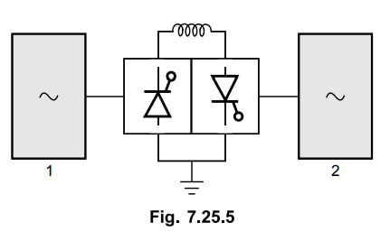
4. Back to back HVDC coupling system
In this system there is no dc
transmission line but the rectification and inversion is done in the same
substation. It is shown in the Fig. 7.25.5.
5. Multiterminal HVDC system
It has three or more terminal
substations. It is shown in the Fig. 7.25.6.

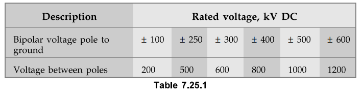
5. Standard Rated Voltages for HVDC System
The bipolar HVDC line has two
conductors, one of positive polarity with respect to earth and other has
negative polarity . The voltage between the poles is twice that of the pole to
earth voltage. Hence bipolar HVDC system is given as ± 500 kV. The standard
rated voltages are given in the Table 7.25.1.
The following HVDC systems are present
and are operating in India.
1. Vindyachal 500 MW
2. Chandrapur 2 × 500 MW
3. Visakhapatnam 500 MW
4. Sasaram 500 MW
Review Questions
1. With a neat schematic, explain the principle of HVDC system
operation.
AU: Dec.-04, Marls 8
2. What are the advantages and disadvantages of HVDC system?
AU: Dec.-06, 08, 09, 12, 13, 17, May-10, 13, 15, 18, Marks 5
3. Explain the different types of HVDC links in detail.
AU: Dec.-06, 11, 12, 16, 17, May-08, 10, 16, Marks 9
Transmission and Distribution: Unit V: (a) Distribution Systems : Tag: : Principle - Advantages - Disadvantages - Types - Standard Rated Voltages - High Voltage Direct Current Transmission
Related Topics
Related Subjects

Transmission and Distribution
EE3401 TD 4th Semester EEE Dept | 2021 Regulation | 4th Semester EEE Dept 2021 Regulation