Transmission and Distribution: Unit V: (a) Distribution Systems
HVDC Substation
Terminal Equipments of a DC Transmission Line
Questions : 1. Draw the schematic layout of HVDC substation and explain. 2. Discuss the main components of HVDC system.
HVDC Substation
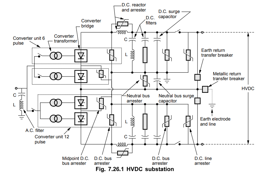
The central equipment of a d.c.
substation is a thyristor converter. There are two such thyristor converter
units. As a separate pole is used for positive and negative (return path) of
d.c., there are two poles and the configuration is called bipole d.c.
substation.
The converter transformers are used to
transform a.c. system voltage to which d.c. system is connected. This ensures
derivation of correct d.c. voltage by converter bridges. The converter
transformers are generally located in switchyard while the converter bridges
are located inside a valve hall. The connection between the two is made with
phase isolated busbars or with wall bushings. When wall bushings are used at
HVDC level of 400 kV or greater then wall bushings must be designed perfectly
and with the care to avoid external or internal insulation breakdown. The
harmonic filters consisting L and C are required on a.c. and d.c. side. The
d.c. reactors are included in each pole of a converter station. They assist
d.c. filters in filtering harmonic currents and smooth the d.c. side current so
that a discontinuous current mode is not reached at low load current operation.
This makes the commutation process of d.c. converter, more robust.
Surge arresters across each valve in the
converter bridge, across each converter bridge and in the d.c. and a.c
switchyard are necessary to protect the equipment from all overvoltages
regardless of their source. Modem HVDC substations use metal-oxide arresters.
The Fig. 7.26.1 shows the layout of a typical HVDC substation
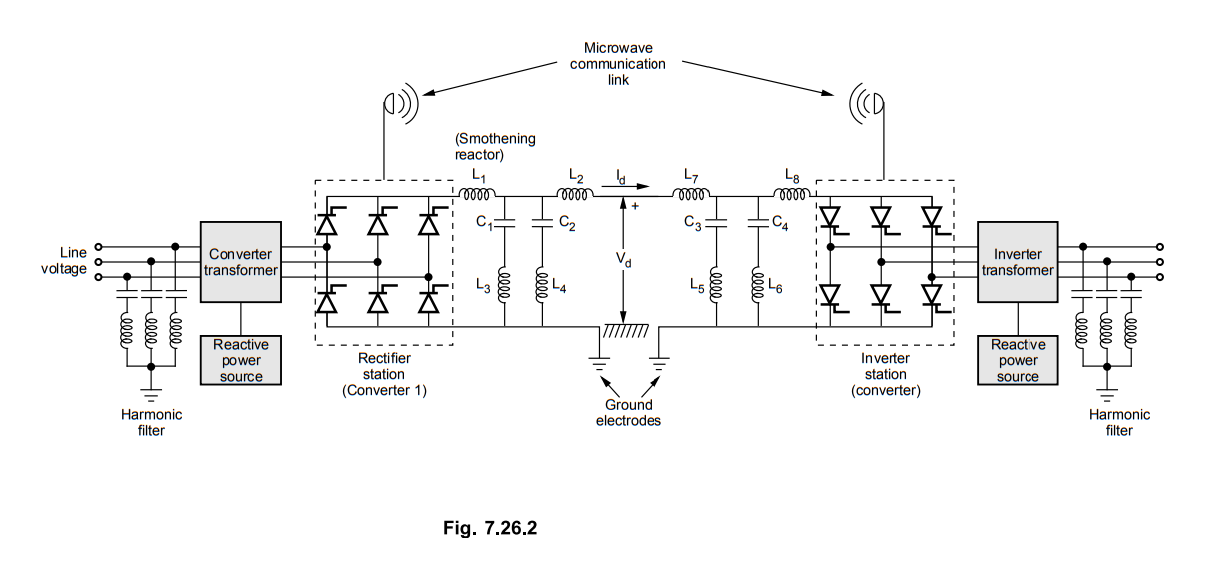
1. Terminal Equipments of a DC Transmission Line
For proper operation of dc transmission
system, various additional auxiliary equipments are required.
These equipments include
1. DC line inductors,
2. Harmonic filters on DC side,
3. Converter transformers
4. Reactive power source,
5. Harmonic filters on AC side,
6. Ground electrodes
7. Microwave communication link between
the converter stations.
The dc transmission line with these
auxiliary equipments is shown in the Fig. 7.26.2.
a. Inductors and Harmonic Filters on DC
Side
On dc and ac side of the dc transmission
system harmonics are produced. Normally 6th and 12th harmonic currents are
produced. If these currents are allowed to flow through line, it may produce
undesirable noise in neighbouring telephone lines. Thus to eliminate these
harmonic currents, harmonic filters are used. This filter consists of two
inductors and a shunt filter which short circuits the harmonic currents to
ground by providing low impedance path.
With the use of these inductors the dc
line current is prevented from increasing rapidly under faulty condition.
The inductors connected in series with
the line are used to smoothen the dc current output of a converter. An air
cored magnetically shielded reactor is used for this purpose.
b. Converter Transformers
The converter transformer is used to
provide ac voltage as required by the converter. Three phase transformers of
the type star-star or star-delta may be used. A third winding called teritiary
winding may sometimes be added for direct connection to source of the reactive
power.
It is required to keep dc line voltage
constant from no load to full load. Also for reducing the reactive power
absorbed by converter the firing angle a should be kept small. It indicates that
the ratio between input AC voltage and output DC voltage of the converter is
fixed. But as dc line voltage is fixed, the input ac line voltage must also be
fixed.
But it may happen that the line voltage
on input ac side may go on varying. Thus the converter transformers on
rectifier side are provided with tappings which will maintain the ac input
voltage nearly constant.
The taps are automatically switched by a
motorised tap changer. The taps are also needed on converter transformer on
inverter side.
c. Reactive Power Source
The variable static capacitors or
synchronous capacitors are required for absorbing reactive power by the
converters. The amount of reactive power required increases with the firing
angle a of a rectifier and the extinction angle y of the inverter. This power
requirement is about 50 % to 60 % of real power transfer. The reactive power
consumption is provided by capacitors, filters or synchronous compensators. As
the active power transmitted goes on varying, the reactive power must also be
varied.
d. Harmonic Filters on AC Side
The three phase, 6-pulse converters
produce 5th, 6th, 11th and 13th order harmonics on AC side. These currents are
undesirable from the point of view of telephone interference. These currents
are bypassed through low impedance filters connected between three phase lines
and ground. The filters for each frequency are connected in star and the
neutral point is grounded.
e. Ground Electrode
Proper attention must be given towards
the ground electrode at each end of dc line. DC currents in the ground have a
corrosive effect on pipes, cables and metallic structures. In order that the dc
ground current does not produce any local problem around the station, the
actual ground electrode is located away from converter station.
At the grounding site, special means are
used to minimize electrode resistance. When bipolar system is temporarily used
as monopolar system, the ground current may exceed which may produce excessive
heat then this electrode resistance factor is important.
f. Communication Link
For Controlling purpose of the
converters at both the ends of the line, a communication link between them is
necessary, e.g. to maintain the current margin AI, the inverter side must know
what is rectifier current setting is. This information is continually relayed
by a high speed communication link between the two converters.
Review Questions
1. Draw the schematic layout of HVDC substation and
explain.
2. Discuss the main components of HVDC system.
Transmission and Distribution: Unit V: (a) Distribution Systems : Tag: : Terminal Equipments of a DC Transmission Line - HVDC Substation
Related Topics
Related Subjects

Transmission and Distribution
EE3401 TD 4th Semester EEE Dept | 2021 Regulation | 4th Semester EEE Dept 2021 Regulation