Digital Logic Circuits: Unit II: Combinational Circuits
Implementation of Logic Functions using Logic Gates
Symbol, Boolean Expression, Truth Table, Operation function, Example Problems
Implementation of Logic Functions using Logic Gates
Implementation of Logic Functions using Logic Gates
1. Summary of Logic Gates
•
Logic gates are the basic elements that make up a digital system. The
electronic gate is a circuit that is able to operate on a number of binary
inputs in order to perform a particular logical function. The types of gates
available are the NOT, AND, OR, NAND, NOR, exclusive-OR, and the exclusive-NOR.

Note
:
EX-OR and EX-NOR gates are also known as mutually exclusive gates.
2. Universal Gates
•
The NAND and NOR gates are known as universal gates, since any logic function
can be implemented using NAND or NOR gates.
•
The simplified Boolean expression can be implemented using basic gates. When we
implement logic circuit using basic gates, we require ICs for AND, OR and NOT
gates. Many times it may happen that all gates from the IC packages are not
required to build the circuit and thus remaining gates are unused. Thus, the
utility factor is very poor. This utility factor is more when we use only one
logic gate (universal gate) to implement the entire logic circuit.
a.
NAND Gate
•
The NAND gate can be used to generate the NOT function, the AND function, the
OR function and the NOR function.
NOT
Function
•
An inverter can be made from a NAND gate by connecting all of the inputs
together and creating, in effect, a single common input, as shown in Fig.
3.9.2, for a two-input gate.

AND
Function :
An
AND function can be generated using only NAND gates. It is generated by simply
inverting output of NAND gate; i.e. 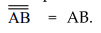 Fig. 3.9.3 shows the two input AND
gate using NAND gates.
Fig. 3.9.3 shows the two input AND
gate using NAND gates.

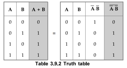
OR Function :
OR
function is generated using only NAND gates as follows : We know that Boolean
expression for OR gate is
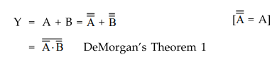
=
A • B DeMorgan's Theorem 1
The
above equation is implemented using only NAND gates as shown in the Fig. 3.9.4.

Note
:
Bubble at the input of NAND gate indicates inverted input.
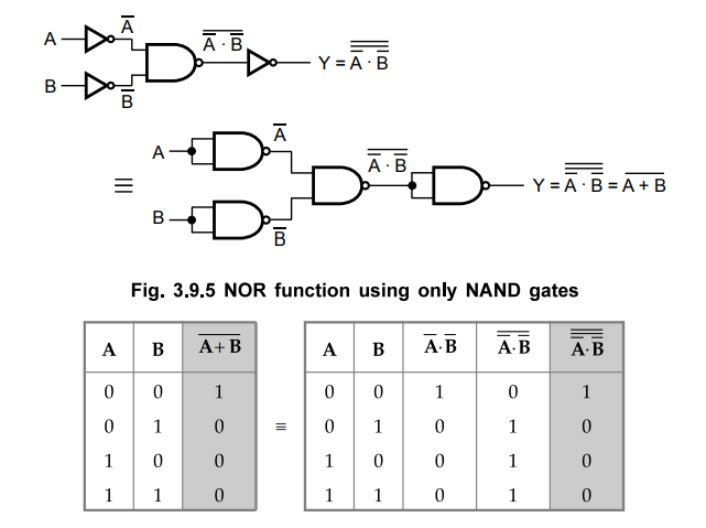
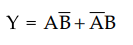
NOR Function :
NOR
function is generated using only NAND gates as follows : We know that Boolean
expression for NOR gate is
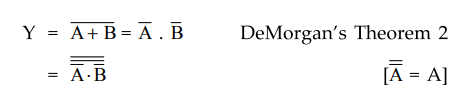
The
above equation is implemented using only NAND gates, as shown in the Fig.
3.9.5.
Examples
for Understanding
Ex.
3.9.1 Implment EX-OR gate using only NAND gates.
Sol.:
The
Boolean expression for EX-NOR gate is
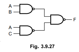
We
can implement AND-OR logic by using NAND-NAND logic as shown in Fig. 3.9.6 (b)

Ex.
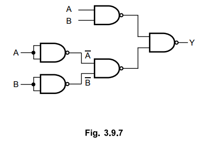
3.9.2 Implement EX-NOR gate using only NAND gates.
Sol.:
The
Boolean expression for EX-NOR gate is 
EX-NOR
gate using only NAND gates as shown in the Fig. 3.9.7.
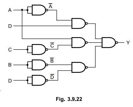
Ex.
3.9.3 Construct the EX-OR gate using 4-NAND gates only, Boolean expression for
EX-OR gate is 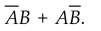 .
.
AU
; May-13, Marks 8
Sol.
:

The
above sum of product expression is implemented using NAND-NAND logic as shown
in the Fig. 3.9.8.

b.
NOR Gate
•
Similar to NAND gate, the NOR gate is also a universal gate, since it can be
used to generate the NOT, AND, OR and NAND functions.
NOT
Function :
An
inverter can be made from a NOR gate by connecting all of the inputs together
and creating, in effect, a single common input, as shown in Fig. 3.9.9.

OR
Function :
•
An OR function can be generated using only NOR gates. It can be generated by
simply inverting output of NOR gate; i.e. 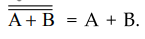 . Fig. 3.9.9 (a) shows the two
input OR gate using NOR gates.
. Fig. 3.9.9 (a) shows the two
input OR gate using NOR gates.

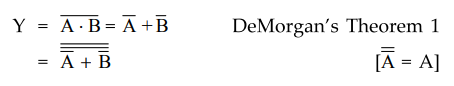
AND
Function :
•
AND function is generated using only NOR gates as follows : We know that
Boolean expression for AND gate is
•
The above equation is implemented using only NOR gates as shown in the Fig.
3.9.10.
Note
:
Bubble at the input of NOR gate indicates inverted input.

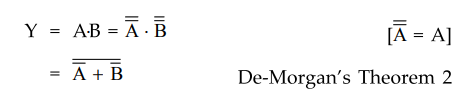
NAND
Function :
NAND
function is generated using only NOR gates as follows : We know that Boolean
expression for NAND gate is
The
above equation is implemented using only NOR gates, as shown in the Fig.
3.9.11.

Examples
for Understanding
Ex.
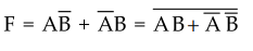
3.9.4 Implement EX-NOR gate using only NOR gates.
Sol.
:
The Boolean expression for EX-NOR gate is :
We
can implement OR-AND logic by using NOR-NOR logic, as shown in Fig. 3.9.12 (b).

Ex.
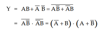
3.9.5 Implement EX-OR gate using only NOR gates.
Sol.
:
Boolean expression of EX-OR gate
Complement
of EX-NOR gate is EX-OR gate
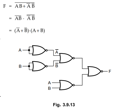
Note
:
We can implement OR-AND logic by NOR-NOR logic.
Ex.
3.9.6 Implement the following Boolean function with NAND-NAND logic
Y
= AC + ABC + ABC + AB + D
Sol.
:
Step
1 :
Simplify the given Boolean function.
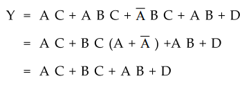
Step
2 : Implement
using AND-OR logic.
Step
3 :
Convert AND-OR logic to NAND-NAND logic.
Ex.
3.9.7 Implement the following Boolean function ith NAND – NAND logic
Sol.
:
Step
1 :
Implement Boolean function with AND-OR logic.
Step
2 :
Convert AND-OR logic to NAND-NAND logic.
Note
:
It is possible to directly go to step 2 skipping step 1. Here, step 1 is
included for clear understanding.
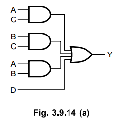
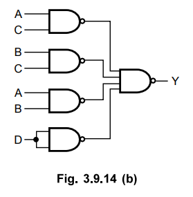
Ex.
3.9.8 Implement the following Boolean function with NOR-NOR logic
Y
= AC + BC + AB + D.
Sol.
:
Step
1 :
Express Boolean function in POS form. Using duality theorem we get,
Step
2 :
Implement Boolean function with OR-AND logic.
Step
3 :
Convert OR-AND logic to NOR-NOR logic.
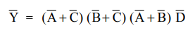
Ex.
3.9.9 Implement the following Boolean function with NOR-NOR logic
Sol.
:
Step
1 :
Implement Boolean function with OR-AND logic.

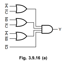
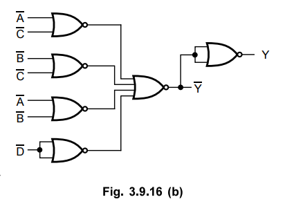
Step
2 :
Convert OR-AND logic to NOR-NOR logic.
Note
:
It is possible to directly go to step 2 skipping step 1. Here, step 1 is
included for clear understanding.
Ex
3.9.10 Simplify and implement the following SOP function using NOR gates,
f
(A, B,C,D) = ∑ m (0, 1, 4, 5, 10, 11, 14, 15)
AU
: May-12, Marks 10
Sol.
:
Step
1 :
Convert SOP function into its equivalent POS function.
∑
m (0, 1, 4, 5, 10, 11, 14, 15) = n M (2, 3, 6, 7, 8, 9, 12, 13)
Step
2 : K-map simplification :

Note
We can convert OR-AND logic into NOR-NOR logic.
Ex.
3.9.11 Simplify and implement the following POS function using NAND gates,
f
(A, B,C,D) = nM (0, 1, 2, 3, 12, 13, 14, 15)
Sol.
:
Step
1 :
Convert POS function into its equivalent SOP function.
II
M (0, 1, 2, 3, 12, 13, 14, 15) = ∑ m (4, 5, 6, 7, 8, 9, 10, 11)
Step
2 : K-map simplification :

Ex.
3.9.12 Using K-map simplify the expression
Y(A,
B, C, D) = m1 + m3 + m5 + m7 + m8
+ m9 + m0 + m2 + m10 + m13
Indicate
the prime implicants, essential and non-essential prime implicants. Draw the
logic circuit using AND-OR-INVERT gates and also using NAND gates.
Sol.
:

Logic
circuit : Using NAND gate
We
can implement AND-OR logic by using NAND-NAND logic
Ex.
3.9.13 Give the simplified expression for the following logic equation where d
represents don't care condition.
f(A,
B, C, D) = Σm(0, 8, 11, 12, 15) + d(1, 2, 4, 7, 10, 14)
Represent
the simplified expression using logic gates.
Sol.
: K-map Simplification :

Ex.
3.9.14 Prove that  is exclusive
OR operation and it equals
is exclusive
OR operation and it equals 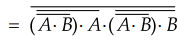
Sol.
: The
truth table for expression 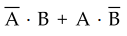 matches with the truth table for
exclusive-OR gate and hence we can say the given expression represents
exclusive-OR operation.
matches with the truth table for
exclusive-OR gate and hence we can say the given expression represents
exclusive-OR operation.

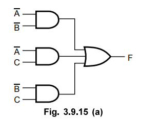
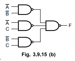
Ex. 3.9.15 Using K-map simplify the following function and implement the function using logic gates
f(A,
B, C) = π(0, 4, 6).
Sol.

Examples
for Practice
Ex.
3.9.16 Implement the following function with NAND gates. F(x,y,z) = (0,6)
Ans.
:

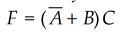
Ex. 3.9.17 Design a logic circuit to simulate the function (A, B, C) = A(B + C) by using only NAND gates.
Ans
. :
Review Questions
1. Write the logic symbol, expression and truth table for the
following logic gates :
1. i) EX-OR ii) NOR
2. i) NANO ii) EX-NOR
3. i) NAND ii) NOR iii) EX-OR
2. What are universal gates ? Give examples.
3. Why NAND and NOR gates are called universal gates?
4. Why digital circuits are more frequently constructed with
NAND or NOR gates than with AND and OR gates ?
5. Realize i) AND gate ii) NOR gate using onl NAND gates.
6. Realize i) OR gate ii) EX-OR gate using NAND gates.
7. Realize i) OR gate ii) AND gate using only NOR gates.
Digital Logic Circuits: Unit II: Combinational Circuits : Tag: : Symbol, Boolean Expression, Truth Table, Operation function, Example Problems - Implementation of Logic Functions using Logic Gates
Related Topics
Related Subjects

Digital Logic Circuits
EE3302 3rd Semester EEE Dept | 2021 Regulation | 3rd Semester EEE Dept 2021 Regulation