Transmission and Distribution: Unit I: Transmission Line Parameters
Inductance of a Single Phase Two Wire Line
Transmission Line Parameters
One conductor is forming a return circuit for the other. The two conductors are carrying currents I1 and I2 respectively.
Inductance of a Single
Phase Two Wire Line
AU : May-05, 07, 08, Dec.-15, 17
Consider a single phase line consisting
of two parallel conductors. These conductors are forming a rectangular loop of
one turn. These conductors are solid conductors of radii rx and r2
respectively. One conductor is forming a return circuit for the other. The two
conductors are carrying currents I1 and I2 respectively.
In a single phase circuit we have
I1
+ I2 — 0
I2 = -I1
Here we are neglecting the effect of
earth's presence of magnetic field geometry as earth's relative permeability is
same as that of air and its conductivity is relatively small.
The arrangement of the conductors and
variation of flux density due to each conductor is shown in the Fig. 1.12.1
respectively.
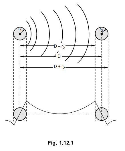
In the beginning, let us consider only
the flux linkages of the circuit caused by the current in conductor 1. The flux
line set up by the current flowing in conductor 1 at a distance equal to or
greater than D + r2 from the center of conductor 1 does not link the
circuit and hence is not responsible for inducing any voltage in the circuit.
This is because conductor 2 carries current which is equal and opposite to that
in conductor 1.
The external flux from r1 to
D-r2 links all the current I1 in conductor 1. Over the
surface of conductor 2 i.e. between (D - r2) and (D + r2),
the external flux links a current whose magnitude is progressively reduces from
I1 to zero because of negative current in conductor 2.
The total inductance of the current
carrying in conductor 1 can be calculated by assuming that D is much greater
than r1 and r2. Under this condition it can be assumed
that flux from (D - r2) to the centre of conductor 2 links current
Ij and flux from the centre of conductor 2 to (D + r2) links zero
current.
The inductance due to current in
conductor 1 can be calculated by using the relation,
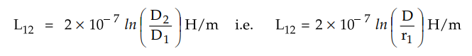
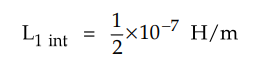
This expression is valid for external
flux only. For internal flux we have,
The total inductance of the circuit due
to current in conductor 1 only is,
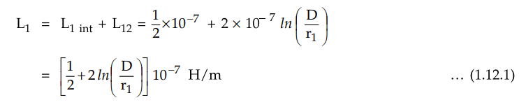
The above equation can conveniently be
written as,
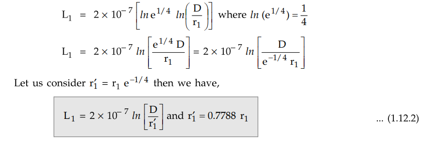
The radius r1 is that of an
imaginary or fictitious conductor assumed to have no internal flux. The
quantity ε-1/4 equals to 0.7778.
The radius r1 is called
Geometric Mean Radius (GMR) of a conducter.
The value of inductance given by
equation (1.12.2) is same as that given by equation (1.12.1). The difference is
that equation (1.12.2) omits the term on account of internal flux. But it is
compensated by adjusted value of radius of conductor.
The above equation is derived by
considering solid round conductors. Equation (1.12.2) is algebraic manipulation of equation (1.12.1). Hence the
multiplying factor of 0.7778 is applicable only to solid round conductors in
order to account for internal flux.
The conductor 2 carries current in
opposite direction to that in conductor 1. The flux linkages produced by
current in conductor 2 considered alone are in the same direction as those
produced by current in conductor 1.
The resultant flux for the two
conductors is determined by sum of m.m.f.s of the two conductors. If
permeability is assumed to be constant then the flux linkages and inductances
of the two conductors calculated separately may be added.
The inductance of conductor 2 in
comparison with equation (1.12.2) can be written as,
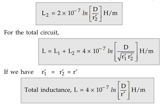
The above equation gives the inductance
of two wire single phase line taking into consideration the flux linkages
caused by current in both the conductors.
The value of inductance obtained is the
inductance per loop meter or per loop mile. The inductance given by equation
(1.12.2) is one half of the total inductance of single phase line and is called
inductance per conductor.
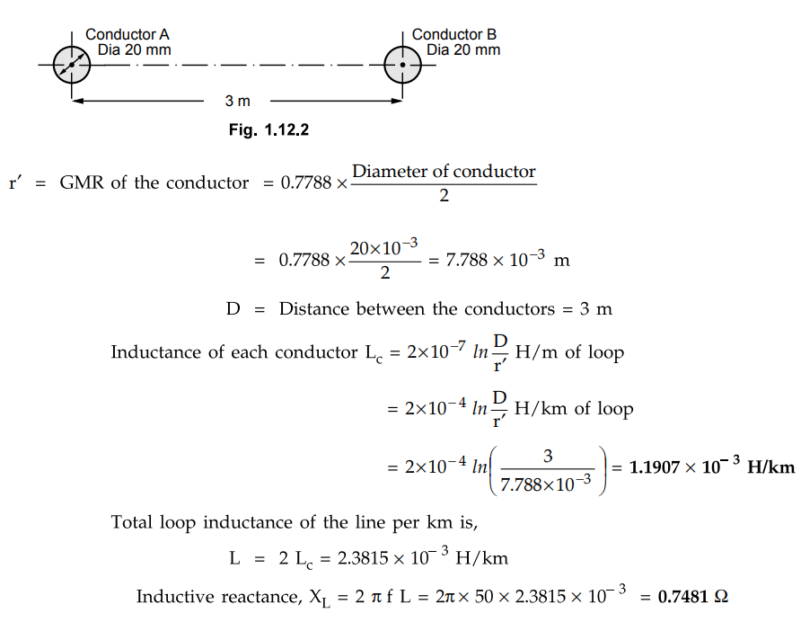
Example 1.12.1
A two conductor single phase line operates at 50 Hz. The diameter of each
conductor is 20 mm and the spacing between the conductor is 3 m. Calculate
i) The inductance of each conductor per
km.
ii) The loop inductance of the line per
km.
iii) The inductive reactance per km.
Solution :
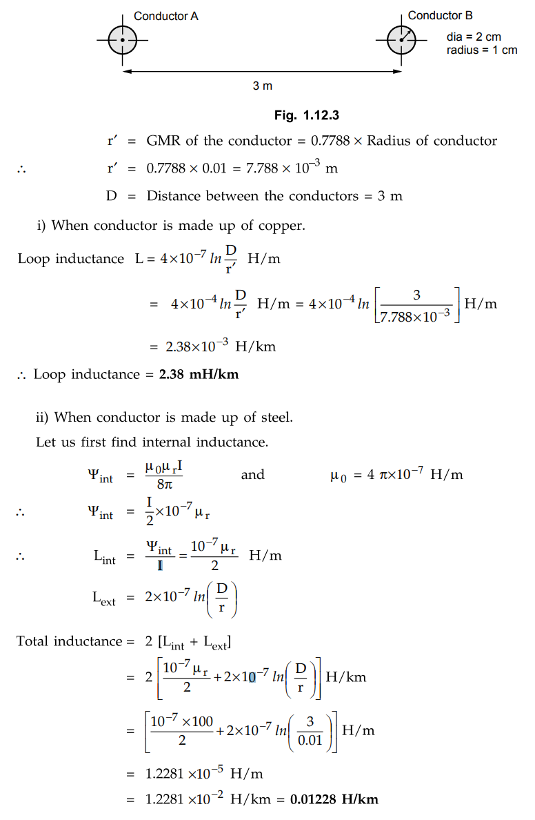
Example 1.12.2
A single phase transmission line has two parallel conductors 3 m apart, the
radius of each conductor being 1 cm. Calculate the loop inductance per km
length of the line if the material of the conductors is 1) copper 2) steel with
relative permeability of 100.
AU : May-07, Marks 8
Solution :
Review Questions
1. Derive the equation for inductance of single phase two wire
line.
2. A single phase line has two parallel conductors 2 meters apart.
The diameter of each conductor is 1.2 cm. Calculate the loop inductance per km
of the line.
(Ans.: 2.423 mH)
3. A single phase transmission line has two parallel conductors 3 m
apart. The radius of each conductor being 1 cm. Calculate the loop inductance
per km length of the line if the material of conductor is copper.
(Ans.: 26.5877 × 10⁻⁴ H/km)
4. Compute the inductance of a single phase line consisting of
conductors of 4 mm diameter each. The spacing between conductors is 1 m. The
line is overhead line and has a length of 5 km.
(Ans.: 0.0129 H)
Transmission and Distribution: Unit I: Transmission Line Parameters : Tag: : Transmission Line Parameters - Inductance of a Single Phase Two Wire Line
Related Topics
Related Subjects

Transmission and Distribution
EE3401 TD 4th Semester EEE Dept | 2021 Regulation | 4th Semester EEE Dept 2021 Regulation