Transmission and Distribution: Unit I: Transmission Line Parameters
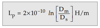
Inductance of Composite Conductor Lines
Now we will consider a single phase 2 wire system. It consists of two conductors say P and Q which are composite conductors.
Inductance of Composite Conductor Lines
Now we will consider a single phase 2
wire system. It consists of two conductors say P and Q which are composite
conductors. The arrangement of conductors is shown in the Fig. 1.14.1.
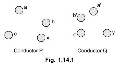
Conductor P is consisting of x
identical, parallel filaments. Each of the filament carries a current of I/x.
Conductor Q consists of y filament with each filament carrying a current of
-I/y. The conductor Y carries a current of I amps in opposite direction to the
current in conductor X as it is forming return path.
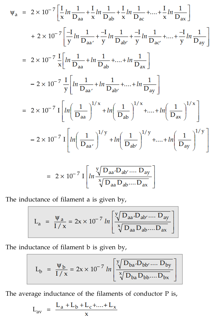
The flux linkages of filament say a due
to all currents in all the filaments is given by
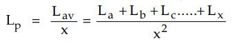
The conductor P consists of x number of
parallel filaments. If all the filaments are of equal inductances then inductance
of the conductor would be 1/x times inductance of one filament. All the
filaments have different inductances but the inductance of all of them in
parallel is 1/x times the average inductance.
Inductance of conductor P is given by,
Substituting the values of La,
Lb .... Lx
in the equation and simplifying the expression we have,
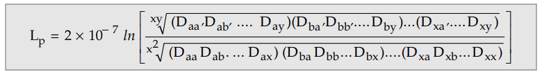
In the above expression the numerator of
argument of logarithm is the xy, the root of xy terms. These terms are nothing
but products of distances from all the x filaments of conductor P to all the y
filaments of the conductor Q.
For each filament in conductor P there
are y distances to filaments in conductor Q and there are x filaments in
conductor P. The xy terms are formed as a result of product of y distances for
each of x filaments. The xyth root of the product of the xy
distances is called the geometric mean distance between conductor P and Q. It
is termed as Dm or GMD and is called mutual GMD between the
conductors.
The denominator of the above expression
is the x2 root of x2 terms. There are x filaments and for
each filament there are x terms consisting of r' (denoted by Daa,Dbb
etc.) for that filament times the distances from that filament to every other
filament in conductor P.
If we consider the distance Daa
then it is the distance of the filament from itself which is also denoted as
1^. This r' of a separate filament is called the self GMD of the filament. It
is also called geometric mean radius GMR and identified as Ds.
Thus the above expression now becomes
Comparing this equation with the
expression obtained for inductance of a single phase two wire line. The distance
between solid conductors of single conductor line is substituted by the GMD
between conductors of the composite conductor line. Similarly the GMR (rQ of
the single conductor is replaced by GMR of composite conductor.
The composite conductors are made up of
number of strands which are in parallel. The inductance of composite conductor
Q is obtained in a similar manner. Thus the inductance of the line is,
L = Lp + LQ
Example 1.14.1
In a single phase line as shown in Fig. 1.14.2 conductors a and a' in
parallel form one conductor and conductors b and b' in parallel form the return
path. Calculate the total inductance of the line per km assuming that current
is equally shared by the two parallel conductors: conductor dia 2 cm.
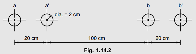
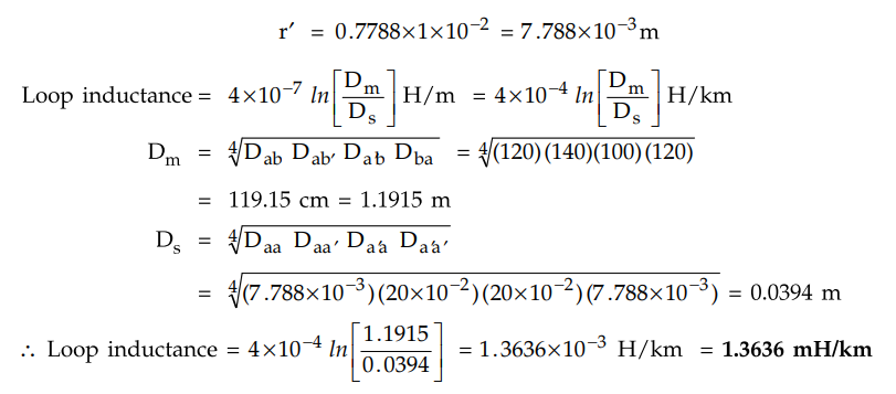
Solution : Distance between conductor a - a' = 20 cm
Diameter of each conductor = 2 cm,
Radius of each conductor = 1 cm
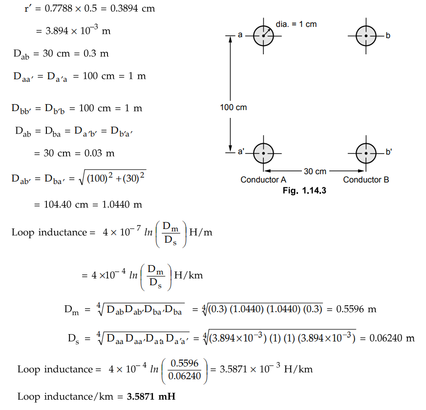
Example 1.14.2
Two conductors of a single phase line, each of 1 cm diameter are arranged in
a vertical plane with one conductor mounted 1 m above the other. A second
identical line is mounted at the same height as the first and spaced
horizontally 30 cm apart from it. The upper and lower conductors are connected
in parallel. Determine the inductance per km of the resulting double circuit.
Solution :
The Fig. 1.14.3 shows the arrangement of conductors. Diameter of each conductor
= 1 cm. Radius of each conductor = 0.5 cm.
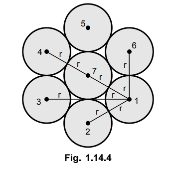
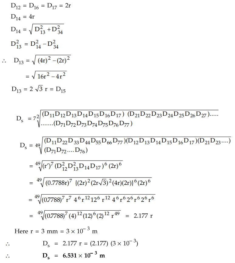
Example 1.14.3 Calculate
the GMR of a conductor having seven strands each of 3 mm radius.
Solution :
Seven stranded conductor is as shown in the Fig. 1.14.4.
Review Questions
1. Derive the expression for the inductance of composite conductor
lines.
2. Prove that the inductance of a group of parallel wires carrying
current can be represented in terms of their geometric distances.
3. Write a short note on concept of GMR and GMD.
4. Distinguish between GMD and GMR.
Transmission and Distribution: Unit I: Transmission Line Parameters : Tag: : - Inductance of Composite Conductor Lines
Related Topics
Related Subjects

Transmission and Distribution
EE3401 TD 4th Semester EEE Dept | 2021 Regulation | 4th Semester EEE Dept 2021 Regulation