Transmission and Distribution: Unit I: Transmission Line Parameters
Inductance of Three Phase Line with Unsymmetrical Spacing but Transposed
Diagram
The drops in the three phases due to these inductances are observed to be different. Thus at the receiving end we will not get the same voltage.
Inductance of Three Phase
Line with Unsymmetrical Spacing but Transposed
Now consider a three phase line having
three conductors but not spaced equilaterally. The problem of finding the
inductance in this case is difficult. The flux linkage and the corresponding
inductance will not be same in each phase. Due to this different inductance per
phase there is imbalance in the circuit though the currents in each phases are
balanced.
The drops in the three phases due to
these inductances are observed to be different. Thus at the receiving end we
will not get the same voltage.
In order to achieve balance under this
case, transposition of transmission line is preferred after a certain fixed
distance. This is shown in the Fig. 1.19.1.
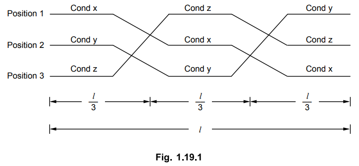
The positions of the conductors are
exchanged at regular interval along the line so that each conductor occupies
the original position of every other conductor over an equal distance. This exchange
of conductor positions is called transposition. Thus balance in the three phase
is restored.
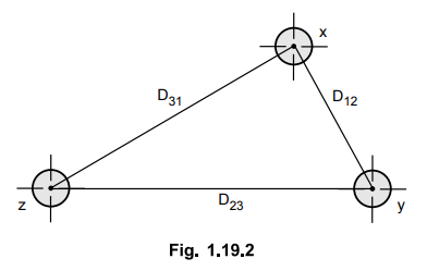
The Fig. 1.19.2 shows complete
transposition cycle. The conductors in the individual phases are denoted by x,
y and z where the positions are given by 1, 2, and 3. The same average
inductance over the complete cycle is obtained due to the transposition.
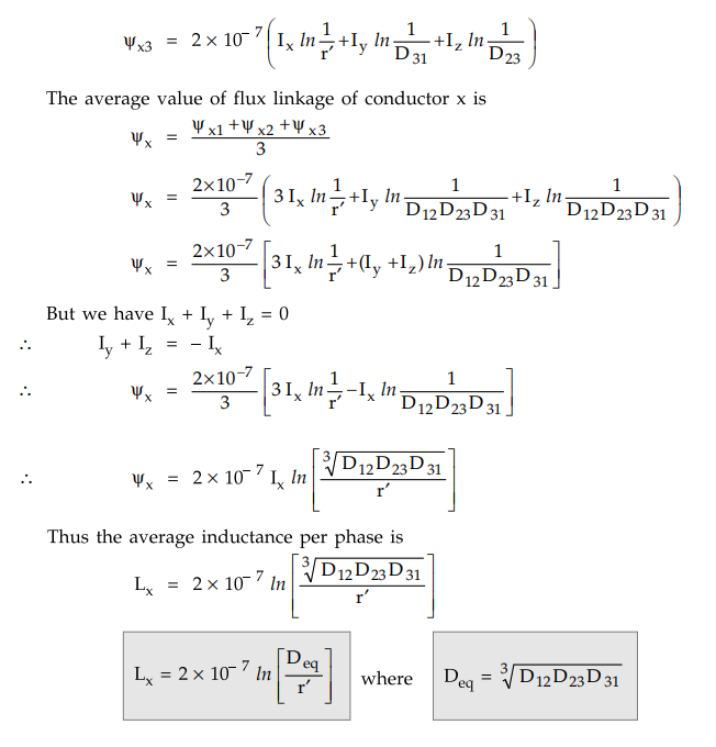
The average inductance of one conductor
is obtained by finding the flux linkages of a conductor for each position that
is occupied during a complete cycle of transposition. Then the average flux
linkages are obtained.
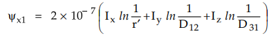
Now let us find the flux linkages of
conductor x which is in position 1 whereas conductor y and z are in positions 2
and 3 respectively.
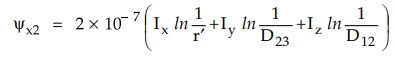
Conductor x is in position 2 whereas
conductors y and z are in positions 3 and 1 respectively.
Conductor x is in position 3 whereas
conductor y and z are in positions 1 and 2 respectively.
In modern power lines, transposition of
lines is not done at regular intervals even though an exchange in conductor
positions can be made at switching stations to balance the inductance per
phase. The inequality in the phases of an untransposed line is small and
neglected in many cases.
If the dissymmetry is neglected, the
inductance of the untransposed line is the average value of the inductive
reactance of one phase of the same line correctly transposed.
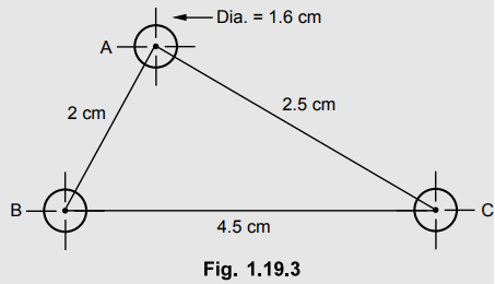
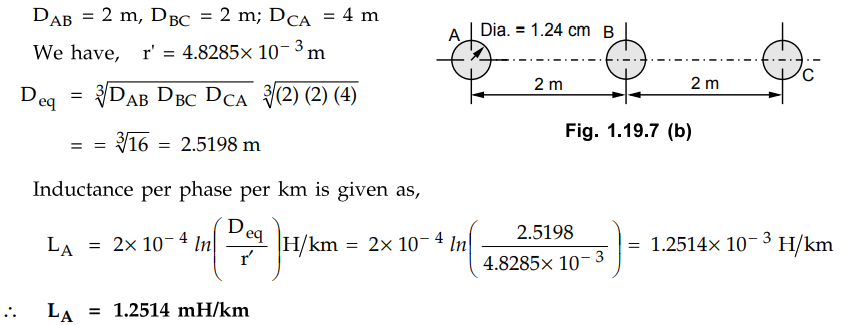
Example 1.19.1
A three phase transmission line has conductor diameter of 1.24 cm each, the
conductors being spaced as shown in the Fig. 1.19.3. The line is carrying balanced
load and it is transposed. Find the inductance of the line per km per phase.
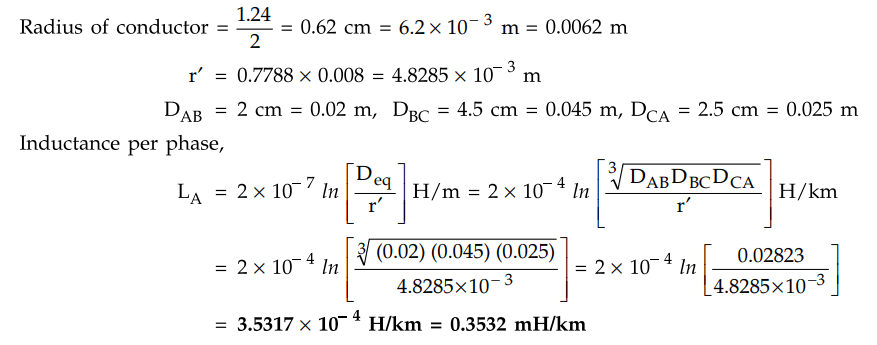
Solution :
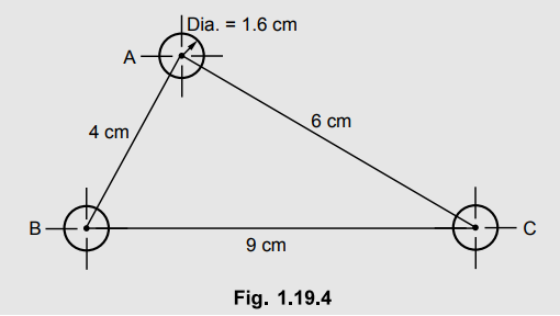
Example 1.19.2
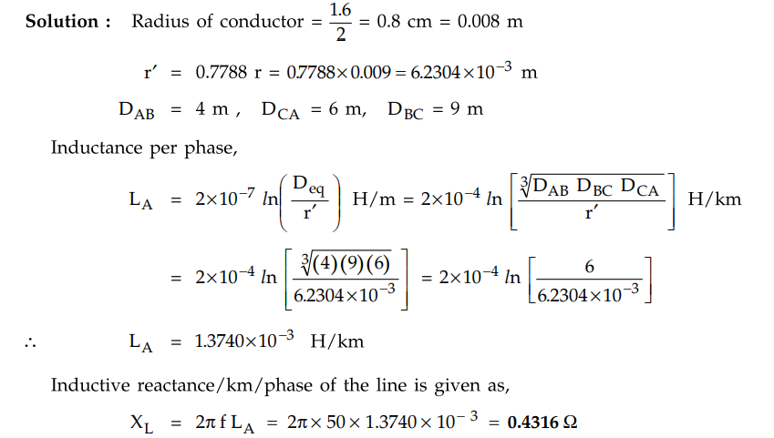
A three phase transmission line has conductor diameter of 1.6 cm each, the
conductors being spaced as shown in the Fig. 1.19.4. The loads are balanced and
the line is transposed. Find the inductance per phase per km of the line and
inductive reactance.
Solution :
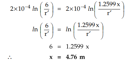
Example 1.19.3 A
three phase line with equilateral spacing of 6 m is to be rebuilt with
horizontal spacing with central conductor is midway between the outers. The
conductors are to be fully transposed. Determine the spacing between adjacent
conductors such that the new line has the same inductance as the original line.
Solution :
Consider the three phase line with equilateral spacing. Let us find the
inductance of this line.
D = Distance between the conductors
= 6 m
Let r be the radius of each of the
conductors.
The inductance of the line per phase per
km is given by,
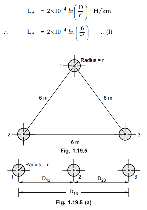
This line is to be rebuilt with horizontal
spacing such that
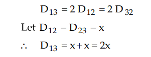
The radius of the conductor remains same
as r.
The inductance per phase per km with
this arrangement is given by,
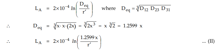
Equating equations (I) and (II) as the
inductance in both the arrangements remains same.
Example 1.19.4 The three conductors of a 3 phase 50 Hz line are arranged with the spacing A - B - 3 m, B - C - 5 m, C - A - 3.2 m. Calculate the inductance and inductive reactors per phase per km of the line. The diameter of each conductor is 25 mm.
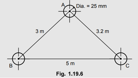
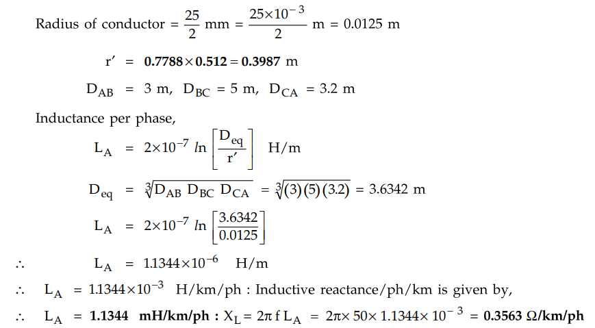
Solution
:

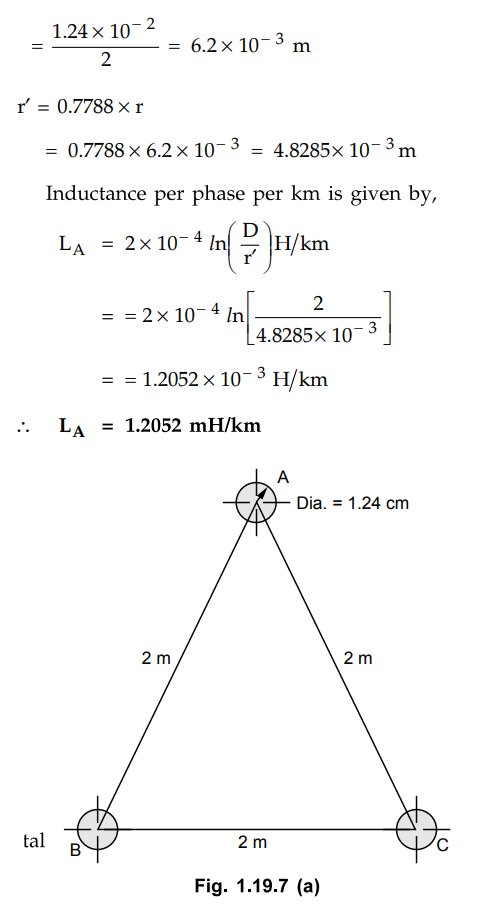
Example 1.19.5 A
50 Hz overhead transmission line consisting of 3 conductors each of diameter
1.24 cm and spaced 2m apart. Calculate the inductance per phase per km for the
following arrangement between conductors :
1) Equilateral spacing 2) Horizontal
spacing.
Assume transposed line.
Solution :
First let's consider the equilateral spacing of conductors.
D = Distance between the conductors = 2
m.
Radius of conductor = Diameter of
conductor / 2
ii) Now let us consider the horizontal
spacing of conductors
Example 1.19.6
Determine the inductance of a 3 phase, line operating at 50 Hz and the
conductors are arranged as shown in Fig. 1.19.8. The conductor diameter is 0.7
cm.
AU : May-05, May-17, Marks 8
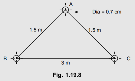
Solution :
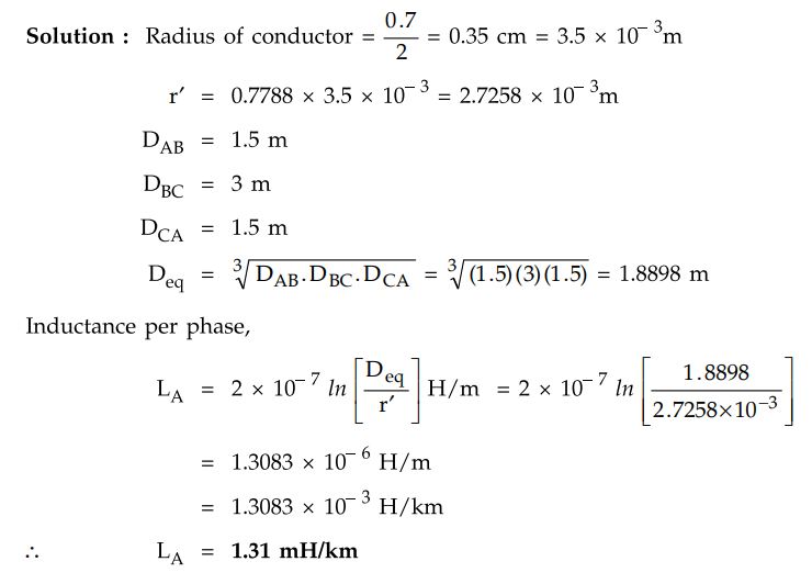
Example 1.19.7
A 3 phase 3 wire over head line consist of 2.5 cm diameter conductors in
horizontal configuration. The line is supplying a balanced load.
i) Find the inductance of each phase
conductor/km length
ii) Why are the inductance of the 3
phases different
iii) What is the significance of
imaginary terms in the expression Assume that the line is not transposed.
Interface spacing is 3 m.
AU : May-10, Marks 16
Solution :
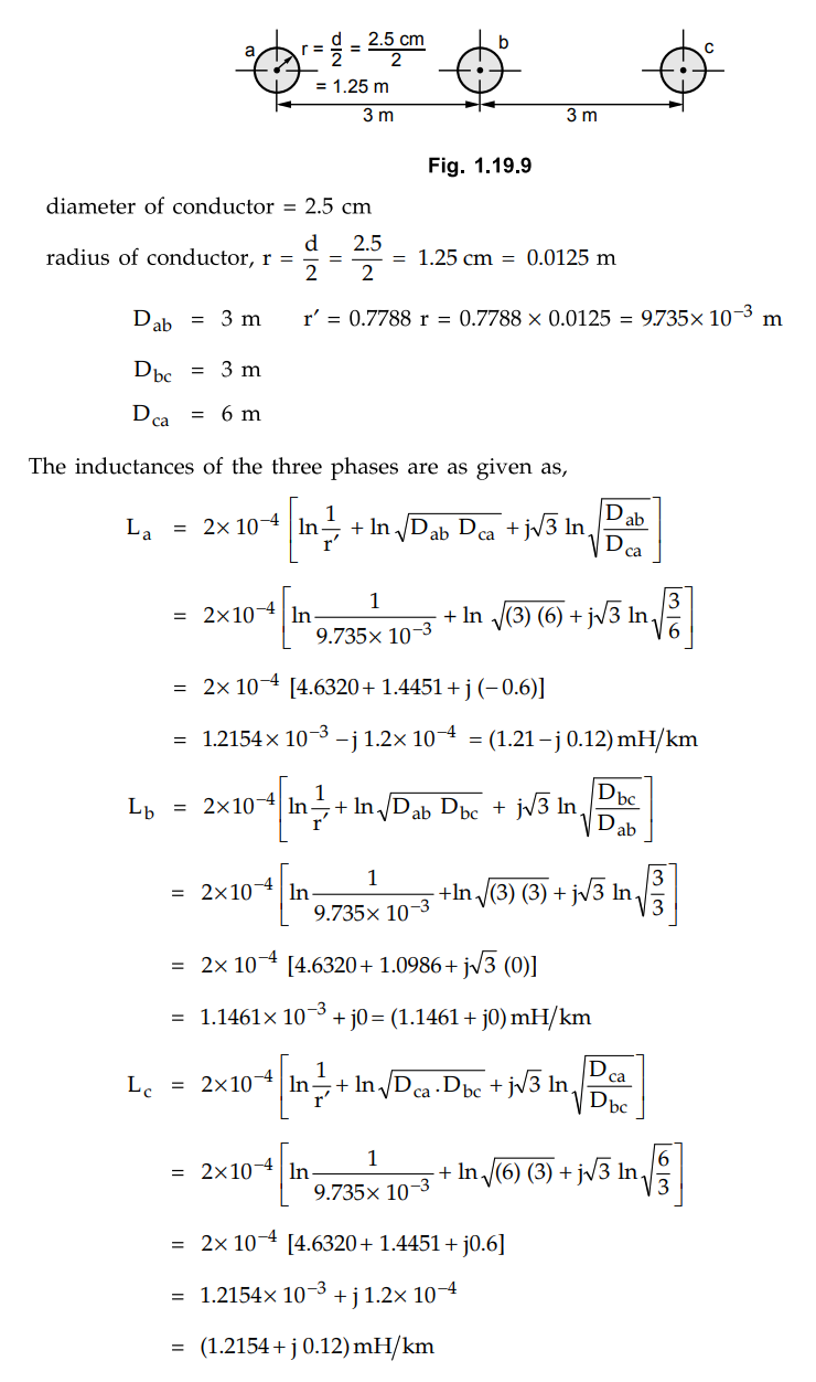
Since the line is not transposed and the
flux linkage in the three phases are not same, the inductance in all three
phases are not same.
The imaginary part in the expression for
inductance represents exchange of energy between phases. It is power
transferred between phases by mutual induction.
The negative imaginary component shows
power is supplied that phase to other phases. The positive imaginary component
shows the power is received by that phase from other phases. Total power
transferred in any case in zero. The mutual power transfer does not affect the
power dissipated in various conductors forming the system.
Review Questions
1. Derive the expression for inductance per phase of a three-phase
overhead transmission line with unsymmetrical spacing between conductors (with
transposition).
2. The three conductors of a three phase line are arranged at the
corners of triangle of sides 4, 5 and 6 metres. Calculate the inductance per km
of each conductor when conductors are regularly transposed. The diameter of
each line conductor is 2 cm. [Ans.:
1.285 mH]
3. Derive expression for the inductance of a 3 phase line with
conductors untransposed. What is the significance of imaginary term in the
expression for inductance ? Hence derive the expressions for inductance for a
completely transposed line.
Transmission and Distribution: Unit I: Transmission Line Parameters : Tag: : Diagram - Inductance of Three Phase Line with Unsymmetrical Spacing but Transposed
Related Topics
Related Subjects

Transmission and Distribution
EE3401 TD 4th Semester EEE Dept | 2021 Regulation | 4th Semester EEE Dept 2021 Regulation