Transmission and Distribution: Unit I: Transmission Line Parameters
Inductance of Three Phase Lines with more than One Circuit
It can be seen that many a times 3 phase transmission lines are working with more than one circuit in parallel.
Inductance of Three Phase
Lines with more than One Circuit
It can be seen that many a times 3 phase
transmission lines are working with more than one circuit in parallel. There is
negligible mutual inductance between the circuits if they are widely separated.
In this case the inductive reactance of the single circuit is half of the
individual circuits considered alone. But in actual case the method of GMD is
used to find inductance of each phase. This is done by considering the
different conductors which are in parallel as strands of one composite
conductor.
If there are more than one circuits in
parallel then it is desired that the equivalent circuit should have low
inductance. This can be achieved with low value of Dm and high value
of Ds. In order to achieve this individual conductors are separated
as widely as possible and the distance between the phases is kept small. Thus
in case of double circuit, conductors are arranged as shown in the Fig. 1.20.1
and not as shown in the Fig. 1.20.2.
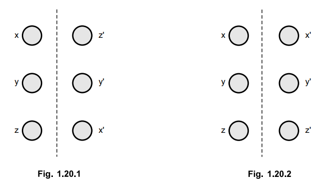
It can be seen that low value of the
inductance is obtained with the arrangement of conductors shown in the Fig.
1.20.1. The use of double circuit increases relibility of power supply. In case
if one of the circuits becomes inoperative due to some reasons then the other
can be used to supply power required. These two three phase circuits are
connected in parallel electrically and are kept on either side of the tower.
Transmission and Distribution: Unit I: Transmission Line Parameters : Tag: : - Inductance of Three Phase Lines with more than One Circuit
Related Topics
Related Subjects

Transmission and Distribution
EE3401 TD 4th Semester EEE Dept | 2021 Regulation | 4th Semester EEE Dept 2021 Regulation