Transmission and Distribution: Unit I: Transmission Line Parameters
Inductive Interference with Neighbouring Circuits
Electromagnetic - Electrostatic Effect - Steps for Reducing Telephone Interference
he transmission lines transmit bulk power with relatively high voltage. Electromagnetic and electrostatic fields are produced by these lines having sufficient magnitude.
Inductive Interference
with Neighbouring Circuits
AU : Dec.-04, 05, 11, 13
In practice it is observed that the
power lines and the communication lines rim along the same path. Sometimes it
can also be seen that both these lines run on same supports along the same
route. The transmission lines transmit bulk power with relatively high voltage.
Electromagnetic and electrostatic fields are produced by these lines having
sufficient magnitude. Because of these fields, voltages and currents are
induced in the neighbouring communication lines. Thus it gives rise to
interference of power line with communication circuit.
Due to electromagnetic effect, currents
are induced which is superimposed on speech current of the neighbouring
communication line which results into distrorion. The potential of the
communication circuit as a whole is raised because of electrostatic effect and
the communication apparatus and the equipments may get damaged due to
extraneous voltages. In the worst situation, the faithful transmission of
message becomes impossible due to effect of these fields. Also the potential of
the apparatus is raised above the ground to such an extent that the handling of
telephone receiver becomes extremely dangerous.
The electromagnetic and the
electrostatic effects mainly depend on what is the distance between power and
communication circuits and the length of the route over which they are
parallel. Thus it can be noted that if the distortion effect and potential rise
effect are within permissible limits then the communication will be proper. The
unacceptable disturbance which is produced in the telephone communication
because of power lines is called Telephone Interference.
There are various factors influencing
the telephone interference. These factors are as follows
1) Because of harmonics in power
circuit, their frequency range and magnitudes.
2) Electromagnetic coupling between
power and telephone conductor.
The electric coupling is in the form of
capacitive coupling between power and telephone conductor whereas the magnetic
coupling is through space and is generally expressed in terms of mutual
inductance at harmonic frequencies.
3) Due to imbalance in power circuits
and in telephone circuits.
4) Type of return telephone circuit i.e.
either metallic or ground return.
5) Screening effects.
1. Electromagnetic Effect
Consider a line transmitting power telephone
line with two conductors E below the power line D and E below conductors. The
two lines are running on the same supports. This is shown in the Fig. 1.35.1.
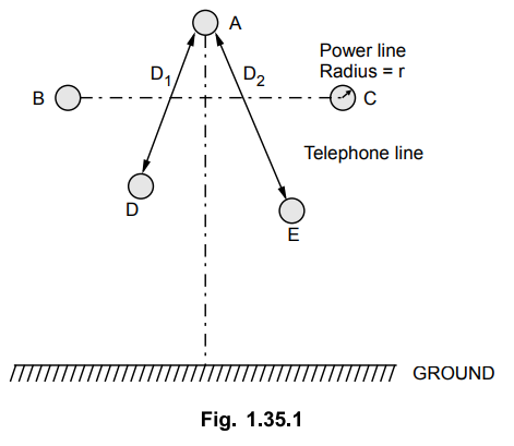
Consider the loop formed by the
conductors A and D. Let the radius of each power line conductor be r. Let the
distance between conductors A and D be D1 whereas the distance between
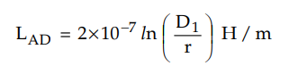
conductors A and E be D2. Assuming that in loop AD, A is
contributing to the emf induced in D. If we neglect the internal flux linkages
then the inductance of this loop is given by,
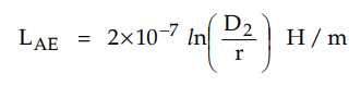
The inductance of the loop AE is given
by,
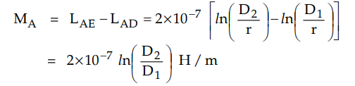
The mutual inductance between conductor
A and the loop DE is given by,
Similarly the mutual inductance between
conductors B and C and loop DE can be obtained. Let these mutual inductances be
MB andMC respectively. These mutual inductances are due to fluxes which have a
phase displacement of 120°. Hence the net effect of the magnetic field will be
M = MA + MB + MC
Here M is the net mutual inductance
which is the phasor sum of the three inductances.
If the current flowing through the power
line conductors is I and the supply frequency is f then the voltage induced in
the communication conductors D and E is given by,
V = 2π f IM volts/m
From the above expression, it can be
seen that with increase in distance between power and communication line, the
values of MA , MB and Me nearly becomes equal in magnitude and with the result
that the net inductance M becomes very very small. As a consequence the voltage
induced in telephone lines also diminishes.
The voltage induced in the neighbouring
telephone line is directly proportional to frequency. If third harmonic is
present then voltage equal to 3 times the voltage due to fundamental frequency
will be induced in telephone lines. Also as the higher frequencies may come
within audible range they produce a distortion effect.
The presence of harmonics and multiples
of third harmonics will not cancel as they are in phase in all power line
conductors. In balanced condition the total induced voltage due to harmonic
currents in power line is additive. In unbalanced condition i.e. during fault
the flux linkage and corresponding voltage induced is very high which may prove
to be dangerous for telephone circuits.
If the distance between power line and
the telephone line is increased then the induced voltage in telephone line can
be reduced. It can also be reduced by transposing the line.
2. Electrostatic Effect
Consider the line conductor A running
parallel to infinite plane (i.e. earth). Let D be the conductor from
neighbouring telephone line. Conductor A' is the image of conductor A below
ground as shown in the Fig. 1.35.2. The potential distribution between the
conductor and earth is exactly same as that of its image and the plane.
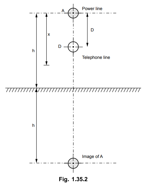
The potential of point A with respect to
the earth is given by,
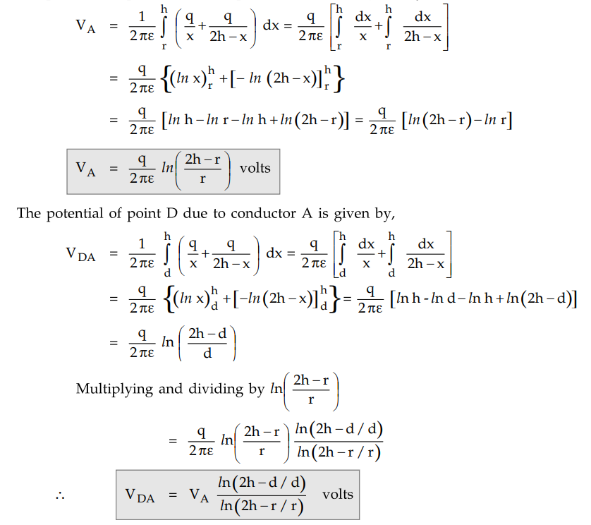
In the similar fashion, the voltages VDB
andVDC can be calculated. Finally the resultant potential of point D with
respect to earth is given by,
VD = VDA + VDB
+ VDC
The above addition is the phasor
addition.
Similarly the resultant potential of
point E, VE can be calculated using the same procedure.
3. Steps for Reducing Telephone Interference
There are various ways that can reduce
the telephone interference. Some of them are as listed below
i) The harmonics at the source can be
reduced with the use of AC harmonic filters, DC harmonic filters and
smoothening reactors.
ii) Use greater spacing between power
and telephone lines.
iii) The parallel rim between telephone
line and power line is avoided.
iv) Instead of using overhead telephone
wires, underground telephone cables may be used.
v) If the telephone circuit is ground
return then replace it with metallic return.
vi) Use microwave or carrier
communication instead of telephone communication.
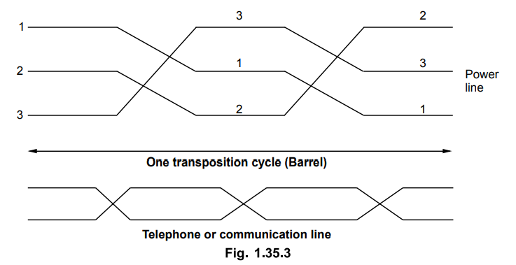
vii) The balance of AC power line is
improved by using transposition. Transposition of lines reduces the induced
voltages to a considerable extent. The capacitance of the lines is balanced by
transposition leading to balance in electrostatically induced voltages. Using
transposition the fluxes due to positive and negative phase sequence currents
cancel out so the electromagnetically induced emfs are diminished. For zero
sequence currents the telephone lines are also transposed which is shown in the
Fig. 1.35.3.
Transposition of conductors proves to be
effective under normal working conditions which may be inadequate under faulty
conditions.
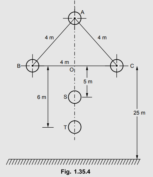
Example 1.35.1
A 3 phase, 60 Hz, 160 km long 132 kV transmission line delivers a total load
of 20 MW at 0.8 pF lagging. The conductor arrangement is as shown in the Fig.
1.35.4. The lowest conductor being 25 m above the ground. The radius of each
power conductor is 0.6 cm. Calculate the induced voltage at fundamental
frequency in the telephone circuit due to electromagnetic effect. Also
determine the potential of telephone conductors S and T above the earth due to
electrostatic effect only.
Solution :
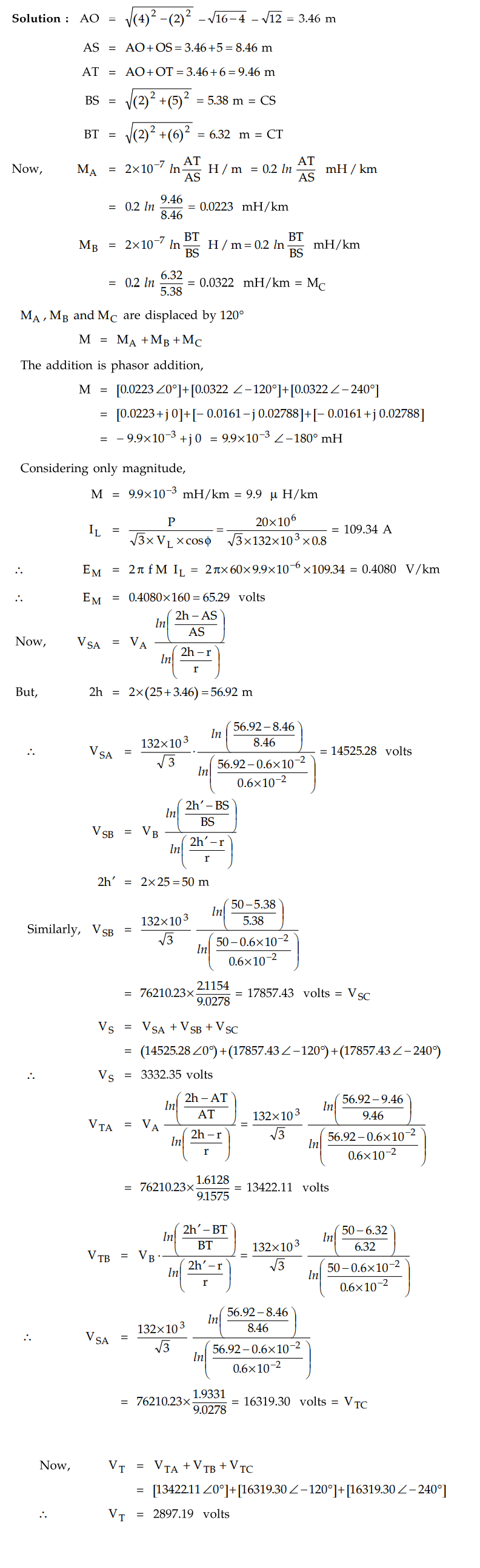
The potential of points above earth is
3332.35 volts.
The potential of point T above earth is
2897.19 volts.
Review Questions
1. Write a short note on inductive interference betweeen
power and communication lines.
AU : Dec.-04, 05, Marks 8
2. Derive the expression for the voltage induced in
communication lines due to the current in power lines.
3. Explain about interference between power and
communication circuits.
Transmission and Distribution: Unit I: Transmission Line Parameters : Tag: : Electromagnetic - Electrostatic Effect - Steps for Reducing Telephone Interference - Inductive Interference with Neighbouring Circuits
Related Topics
Related Subjects

Transmission and Distribution
EE3401 TD 4th Semester EEE Dept | 2021 Regulation | 4th Semester EEE Dept 2021 Regulation