Electron Devices and Circuits: Unit V: (b) Oscillators
LC Oscillators
Principle of Operation
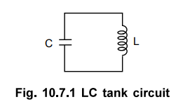
• The oscillators which use the elements L and C to produce the oscillations are called LC oscillators. The circuit using elements L and C is called tank circuit or oscillatory circuit, which is an important part of LC oscillators.
LC Oscillators
•
The oscillators which use the elements L and C to produce the oscillations are
called LC oscillators. The circuit using elements L and C is called tank
circuit or oscillatory circuit, which is an important part of LC oscillators.
This circuit is also referred as resonating circuit, or tuned circuit. These
oscillators are used for high frequency range from 200 kHz upto few GHz. Due to
high frequency range, these oscillators are often used for sources of RF (Radio
Frequency) energy. Let us study the basic action of LC tank circuit first.
1. Operation of LC Tank Circuit
•
The LC tank circuit consists of elements L and C connected in parallel as shown
in the Fig. 10.7.1.
• Let the capacitor is initially charged from a d.c. source with the polarities as shown in the Fig. 10.7.2.
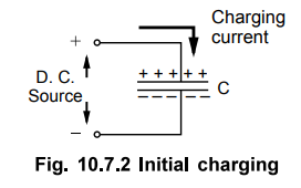
• When the capacitor gets charged, the energy gets stored in a capacitor called electrostatic energy. When such a charged capacitor is connected across inductor L in a tank circuit, the capacitor starts discharging through L, as shown in the Fig. 10.7.3.
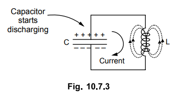
• The
arrow indicates direction of flow of conventional current. Due to such current
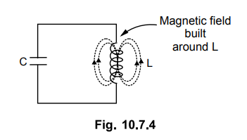
flow, the magnetic field gets set up around the inductor L. Thus inductor
starts storing the energy. When capacitor is fully discharged, maximum current
flows through the circuit. At this instant all the electrostatic energy get
stored as a magnetic energy in the inductor L. This is shown in the Fig.
10.7.4.
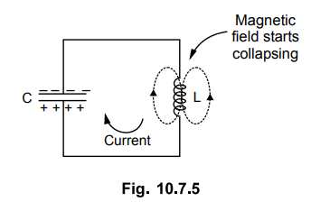
•
Now the magnetic field around L starts collapsing. As per Lenz's law, this
starts charging the capacitor with opposite polarity making lower plate
positive and upper plate negative, as shown in the Fig. 10.7.5.
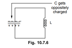
•
After some time, capacitor gets fully charged with opposite polarities, as
compared to its initial polarities. This is shown in the Fig. 10.7.6. The
entire magnetic energy gets converted back to electrostatic energy in
capacitor.
• Now capacitor again starts discharging through inductor L. But the direction of current through circuit is now opposite to the direction of current earlier in the circuit. This is shown in the Fig. 10.7.7. Again electrostatic energy is converted to magnetic energy. When capacitor is fully discharged, the magnetic field starts collapsing, charging the capacitor again in opposite direction.

Key Point : Thus capacitor
charges with alternate polarities and discharges producing alternating current
in the tank circuit.
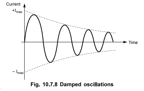
•
This is nothing but oscillatory current. But every time when energy is
transferred from C to L and L to C, the losses occur due to which amplitude of
oscillating current keeps on decreasing everytime when energy transfer takes
place. Hence actually we get exponentially decaying oscillations called damped
oscillations. These are shown in the Fig. 10.7.8. Such oscillations stop after sometime.
Key
Point : In LC oscillator, the transistor amplifier
supplies this loss of energy at the proper times.
•
The care of proper polarity is taken by the feedback network. Thus LC tank
circuit alongwith transistor amplifier can be used to obtain oscillators called
LC oscillators. Due to supply of energy which is lost, the oscillations get
maintained hence called sustained oscillations or undamped oscillations.
•
The frequency of oscillations generated by LC tank circuit depends on the
values L and C and is given by,
f
= 1/ 2π √LC Hz
where
L is in henries and C is in farads.
Electron Devices and Circuits: Unit V: (b) Oscillators : Tag: : Principle of Operation - LC Oscillators
Related Topics
Related Subjects

Electron Devices and Circuits
EC3301 3rd Semester EEE Dept | 2021 Regulation | 3rd Semester EEE Dept 2021 Regulation