Basic Civil & Mechanical Engineering: UNIT IV: b. Boilers
Locomotive Boiler
Description, Working Principle, Layout Diagram
Locomotive boiler is a horizontal, multi-tubular, internally fired, fire tube boiler. Steaming rate is 7000 kg per hour. It is used in railway engines, etc. In railways, the use of locomotive steam engine is being reduced gradually. It is replaced by diesel engines.
LOCOMOTIVE BOILER
Locomotive
boiler is a horizontal, multi-tubular, internally fired, fire tube boiler.
Steaming rate is 7000 kg per hour. It is used in railway engines, etc. In
railways, the use of locomotive steam engine is being reduced gradually. It is
replaced by diesel engines.
Description
[Fig. 2]: A locomotive boiler consists of the following
parts:
1.
Horizontal Cylindrical Shell or Barrel
2.
Fire Box
3.
Smoke Box
4.
Fire Tubes and Water Tubes
5.
Fire Hole
6.
Grate
7.
Steam Dome
8.
Headers
9.
Chimney
10.
Damper
1.
Horizontal Cylindrical Shell or Barrel: The Shell or
Barrel is cylindrical in shape of 1.5 meters in diameter and 4 meters in
length. It is fitted to a rectangular Fire Box.
2.
Fire Box: The fire box is at the right end of the
boiler shell. It forms the furnace.
3.
Smoke Box: The smoke box is at the left end of the
steam shell.
4.
Fire Tubes (Flue Tubes) and Water Tubes: The steam barrel
consists of fire tubes and water tubes. Flue gases flow through the fire tubes.
5. Fire Hole: The fuel, i.e., coal is fed into the barrel through the fire
hole. It is burnt on the Grate which slopes towards the left side.
6.
Grate: Grate is placed at the bottom of the fire box where
coal is burnt.
7.
Steam Dome: It is fitted at the top of the steam
barrel, where the steam will be collected.
8.
Headers: Headers are rectangular boxes. There are
two headers, viz., Superheated Steam Header and Wet Steam Header.
9.
Chimney: The hot gases from the smoke box are
discharged to the atmosphere through a short chimney. The height of the chimney
is kept low so that when the locomotive is passing under a bridge, it does not
hit against the top.
10.
Damper: Function of the damper is to control
the quantity of air entering the fire box.
Working
[Fig. 2]
Fuel,
i.e., coal is introduced into the boiler furnace through the fire hole. The
grate is fitted in an inclined position for charging the coal into the furnace.
A
fire brick arch is fitted to the furnace above the grate. This arch deflects
the flue gases causing them to come in contact more thoroughly with the whole
heating surface of the furnace.
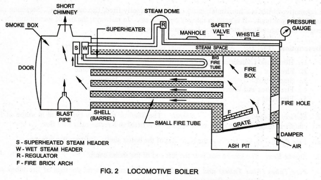
The
flue gases from the furnace pass through the flue tubes to the smoke box. Flue
gases from the smoke box are led to the atmosphere through the chimney. The
path of the flue gases is shown by arrows in the Figure.
Due
to the continuous flow of hot gases from the fire box to fire tubes, water
surrounding the tubes becomes more and more heated and wet steam is produced.
The wet steam enters the wet steam header.
To
remove the moisture in the wet steam and thereby, to increase the temperature
of steam, it is superheated. From the wet steam header, steam flows through
superheater tube, provided in the big fire tube.
The
superheated steam is accumulated in superheated steam heacter. It is then led
to the engine cylinder. Inside the steam dome, there is a steam stop valve in
the regulator. This valve is regulated by a regulating rod to allow the
required quantity of steam to pass. Regulator is operated by the driver from
the cabin by a hand wheel.
A
blast pipe is provided at the bottom of the smoke box. The exhaust waste steam
from the engine cylinder enters the blast pipe and flows out, expanding with a
high velocity. Due to the expansion of waste steam, a partial vacuum is created
within the smoke box. This vacuum improves the movement of waste flue gases and
rapidly removes the waste flue gases from within the smoke box through the
chimney. This vacuum also draws in atmospheric air through the fuel in the
furnace.
The
boiler is fitted with a pressure gauge, safety valve, water level indicator,
whistle, fusible plug, blow-off cock and manhole.
Basic Civil & Mechanical Engineering: UNIT IV: b. Boilers : Tag: : Description, Working Principle, Layout Diagram - Locomotive Boiler
Related Topics
Related Subjects

Basic Civil and Mechanical Engineering
BE3255 2nd Semester 2021 Regulation | 2nd Semester EEE Dept 2021 Regulation