Electric Circuit Analysis: Model Question and Answer
Model Question and Answer - 1 PART B
Electric Circuit Analysis
Electric Circuit Analysis:Model Question and Answer Part-B
MODEL QUESTION AND ANSWER
PART-B (5 × 16 = 80 MARKS)
11.a (i) Solve for V1 and V2, using nodal method for the circuit in the Figure. V = 100 Volts. (8)
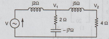
Ans: There are only two principal nodes. One of them is taken as reference. At the other one (node 1) applying KCL, we get
V1-V / j2 + V1 / 2-j7 + V1 / 4+j5 = 0
=> V1 [1/j2 + ½-j7 + ¼+j5 ] = V/j2
= 100/j2
= 50 ∠ -90o
=>V1 [-j0.5 + 2+ j7/53 + 4 - j5/41] =50 ∠ -90o
⇒ V1 [-j0.5 + 0.1353 + j0.01 ] = 50 ∠ -90°
⇒ V1 50 ∠ -90o / 0.1353 - j0.49
= 50 ∠ -90o / 0.5083 ∠ -15o
V2 = V1 × 4 / 4 + j5
= 98.36 ∠ -15° × 4 / 6.4 ∠ 51.3°
= 61.5 ∠ -66.3° volts
(ii) Using mesh analysis, find current through 4Ω resistor in the figure. (8)
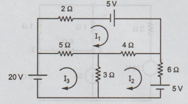
Ans: Let the loop currents be as shown in the Figure. Then the current through
4Ω= I1 - I2
By inspection,
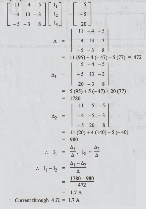
= 11 (20) + 4 (140) - 5 (-40)
= 980
I1 = Δ1 / Δ, I2 = Δ2/Δ
I1 - I2 = Δ1 - Δ2 / Δ
= 1780-980 / 472
= 1.7 A
Current through 4Ω = 1.7 A
(OR)
11. (b) Using nodal analysis find the power dissipated in the 6Ω resistor of the circuit shown.
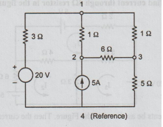
Ans: Let the nodes be numbered as shown.
By inspection,
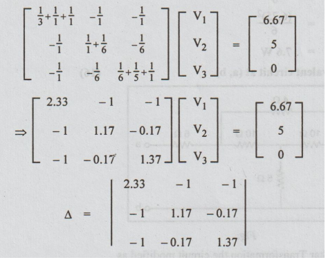
= 2.33 (1.574) + (-1.54) - (1.34)
= 0.787
= 6.67 (1.34) - 5 (-1.396)
= 15.92
V2 = Δ2 / Δ = 21.23 / 0.787 = 26.98 V
V3 = Δ3 / Δ = 15.92 / 0.787
= 20.23 V
Voltage across 6 Ω = V2 - V3
= 6.75 V
V6 = 6.75 volts
Power loss in 6 Ω = (V6)2 / 6
= (6.75)2 / 6
= 7.6 W
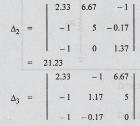
12. (a) Find the Thevenin's equivalent circuit at (a, b). (16)
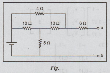
Solution: By applying delta-Star Transformation the circuit modified as
Again the circuit reduced by resistance series connection technique.
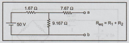
Rth = 1.67 || 9.167 + 7.67
= 9.08 Ω
To find Vth:
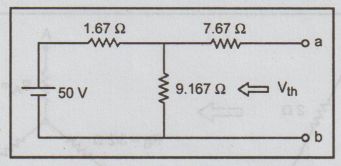
Apply KVL in loop (1),
50 - 1.67 i - 9.167 i = 0
50 = 10.833 i
i = 50 / 10.833 = 4.62 A
Vth = i × R
= 4.62 × 9.167
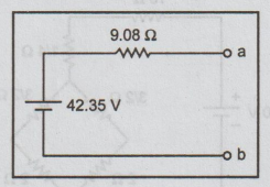
= 42.35 V
Thevenin's equivalent circuit
(OR)
12.(b)For the circuit diagram shown in Fig., Find the current flowing through the 10 Ω resistor. (16)
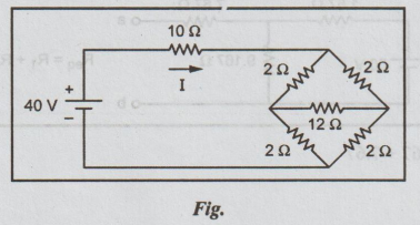
By applying Δ - Y transformation the circuit modified as

Again the circuit reduced as,
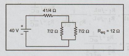
V = 40 V
I = 40 / 12 = 3.33 A
Current through 10 Ω resistor is 3.33 A.
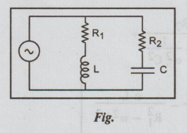
13. (a) For the parallel circuit shown in Fig. find the Resonance frequency, f.
(16)
Solution:
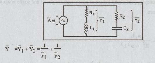
Consider the parallel resonant circuit shown in Fig. excited by a sinusoidal source of variable frequency. Let ![]() be the total admittance see by the source.
be the total admittance see by the source.
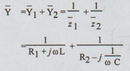
Let us separate the real and imaginary part by multiplying the numerator and denominator of each term by the conjugate of the denominator.
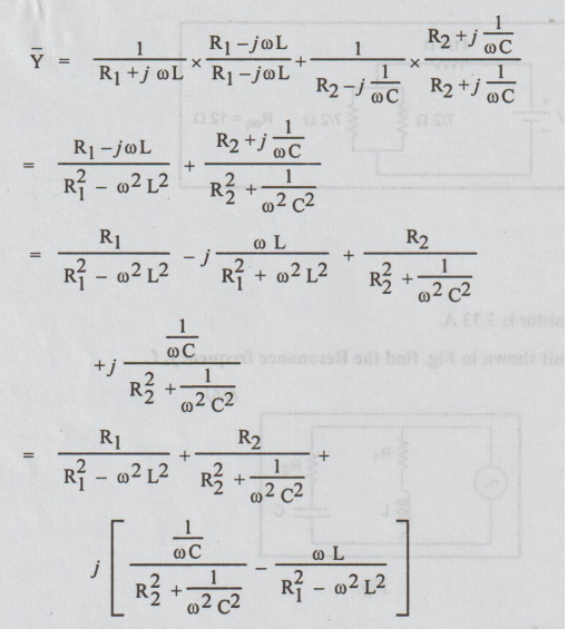
At resonant frequency ωr, the circuit behave as purely resistive circuit and so the imaginary part of the admittance is zero.
At ω = ωr;

On cross multiplying the above equation, we get
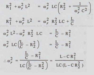
Angular Frequency of resonance
ωr = 1/ √LC √L-CR12/ L – CR22
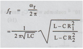
Frequency of resonance,
fr = ωr / 2π
The admittance at resonance
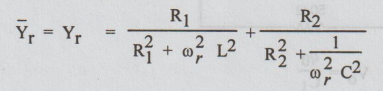
Dynamic resistance Rdy = 1 / Yr
Resonance at all Frequencies
The parameter R1, R2, L and C of the parallel resonant circuit shown in the Fig. can be chosen such that the circuit behave as purely resistive circuit at all frequencies. Hence the circuit will be in resonance at all frequencies.
From Equation
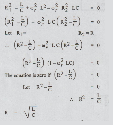
We can say that when R1 = R2 = L / C , the imaginary part of the admittance will be zero for all frequency and the circuit will behave as resistive circuit at all frequencies (i.e.,) resonate at all frequencies.
[OR]
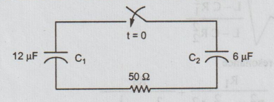
13 b C1 in the figure has an initial charge of q0= 12 × 10-4 coulombs while C2 has no initial charge. The switch is closed at t = 0. Find the current transient.
(16)
Ans :
Initial voltage across C1 = Vo = q0 / C1
= 12 × 10-4 / 12 × 10-6 = 100 volts
After closing the switch the circuit is drawn in S-domain as below.
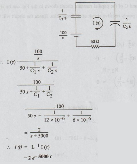
= 2 / s+ 5000
i(t) = L-11(s)
=2e-5000t
14. (a) (i) Show that for a 3-phase delta connected circuit IL =√3 Iph and VL = Vph
(8)
Balanced Delta Connected load
Fig. shows a balanced delta - connected load of impedance Z in each phase.
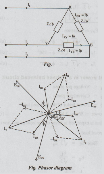
Assume the phase sequence to be RYB. Taking ERY as reference
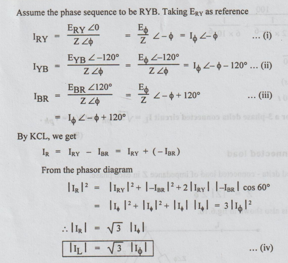
In polar form, taking ERY as reference
IR = √3 Iϕ ∠ -ϕ -30o ...(xii)
IY = √3 Iϕ ∠ -ϕ -150o ...(xiii
IB = √3 Iϕ ∠ -ϕ -90o ...(xiv)
Expression for total power in a 3 phase balanced circuit
Let Eϕ = Voltage per phase
Iϕ = Current per phase
Cos ϕ = Power factor of the balanced load
Total average power = W = 3 Eϕ I cos ϕ... (i)
Usually, this expression is expressed in terms of line voltage and line current as below:
Case (1): Star connected load:
Here EL = √3 Eϕ
Eϕ = EL / √3
and IL = Iϕ
Substituting these values in equation (i)
W = 3EL /√3 IL Cos ϕ
W = √3 EL IL COS ϕ... (ii)
Case (2): Delta connected load :
Here EL = Eϕ
IL = √3Iϕ ⇒ Iϕ = IL /√3
Putting these values in equation (i), we get
W = 3 EL IL / √3 cos ϕ
= √3 EL IL cos ϕ ... (iii)
EL and IL are in volts and amperes respectively.
Then the power W is in watts. Dividing both sides of the equation (iii) by 1000, we get:
W/ 1000 = √3 EL IL / 1000 cos ϕ
W/1000 is actual power or average power or a real power or true power. (denoted by P) in KW.
√3 ELIL / 1000 is apparent power (denoted by S) and measured in KV amperes (KVA).
KW = KVA cos ϕ ... (iv)
From equation (iv), we can draw the power triangle which is shown below:
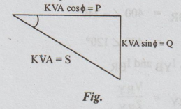
It is right-angled triangle from which we get the relation S = P + jQ
=> S = √ P2 + Q2 ...(v)
Here P = KVA cos ϕ
= active power
Q = KVA sin ϕ
= reactive power and
S = KVA = apparent power
14.. (a) (ii) A balanced delta-connected load of impedance (15+j20) Ω per phase is connected to a three phase, 400 V, 50 Hz supply. Find the line currents and power absorbed by the load. Assume RYB phase sequence. (8)
Solution:
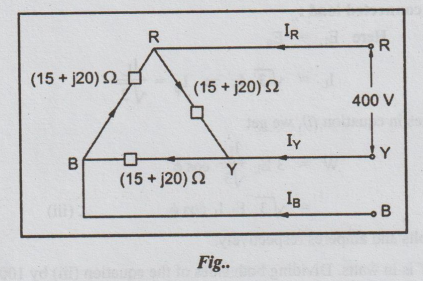
VL = 400 volts
Zload/phase = (15+j20) Ω
Vph = VL = 400 volts
For a phase sequence RYB,
VRY = 400 ∠ 0°
VYB = 400 ∠ -120°
and VBR = 400 ∠ -240°
= 400 ∠ 120°
The phase currents: IRY, IYB and IBR
IRY = VRY /ZRY
= 400 ∠ 0° / 15 + j20
= 400 ∠ 0° / 25∠ 53.13°
= 16∠ -53.13°
= 9.6 - j12.8
IYB= VYB/ZYB = 400 ∠ -120°/ 15 + j20
= 400 ∠ -120o / 25 ∠ 53.13°
= 16 ∠ -173.13°
= -15.9 - j1.91 A
IBR = VBR / ZBR
= 400 ∠ 120° / 25 ∠ 53.13°
= 16 ∠ 66.87° A
= 6.29 + j14.71 A
Line currents are IR, IY and IB. By KCL, we get the phase currents as follows.
IR = IRY - IBR
= (9.6 - j12.8) - (6.29 + j14.71)
= 3.31 - j27.51
= 27.7 ∠ -83.1° A
IY = IYB - IRY
= (-15.9-j1.91) - (9.6 - j12.8)
= -25.5 + j10.89 = 27.7 ∠ 156.9°
IB = IBR - IYB
= (6.29 + j14.71) - (- 15.9 - j1.91)
= 1 + j 16.02
= 22.19 + j16.02
= 27.72 ∠ 36.8° A
VL = 400 V
IL = 27.7 A
Φ = 53.13°
Total power absorbed by the load
= √3 VL IL Cos ϕ
= √3 × 400 × 27.7 × cos 53.1°
= 11523 watts = 11.523 kW
(OR)
14 (b) A three-phase, four-wire, 150 V, CBA system has a Y-connected load, with ZA = 6 ∠ 0°Ω, ZB= 6 ∠ 30°Ω, ZC = 5 ∠ 45° Ω obtain all line currents. (16)
Solution:
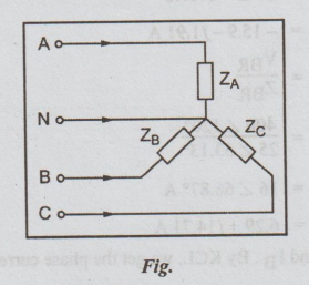
VL = 150 volts
Vϕ = VL/√3 = 150 / √3 = 86.6 volts
Take VBN as reference, then
VAN = 86.64 ∠ -90°
VBN = 86.6 ∠ 30°
and VCN = 86.6 ∠ 150°
IA = VAN / ZA = 86.64 ∠ -90° / 6 ∠ 0o
= 14.43 ∠ -90° A
IB = VBN / ZB = 86.6 ∠ 30° / 6 ∠ 30°
= 14.43 ∠ 0° A
IC = VCN / ZC
= 86.6 ∠ 150° / 5 ∠ 45°
= 17.32 ∠ 105°
IN = - (IA + IB + IC)
= -[14.43 ∠ -90° + 14.43 ∠ 0° + 17.32 ∠ - 105°]
= - [-j14.43 + 14.43 - 4.48 + j16.73]
= - (9.95+j2.3)
= -9.95 – j2.3
=10.21 ∠ -167° A
15. (a) Explain the single tuned and double tuned circuit.
Tuned circuits are classified as:
(i) Single tuned circuits
(ii) Double tuned circuits
Single Tuned Circuit
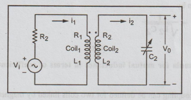
Consider the single tuned circuit as shown in the Fig. It consists of coil 1 on the primary side and a tank circuit on the secondary side. The tank circuit consists of coil 2 and a capacitor. The coil 1 and the resonant circuit are inductively coupled. The coil 1 is excited by a source voltage Vi and the output is taken across the capacitor C2. Let the source resistance be R2, R1 and L1 are resistance and inductance of coil 1, R2 and L2 are resistance and inductance of coil 2. The mutual inductance between coil 1 and coil 2 is given by
M = K√ L1 L2
Double Tuned Circuits
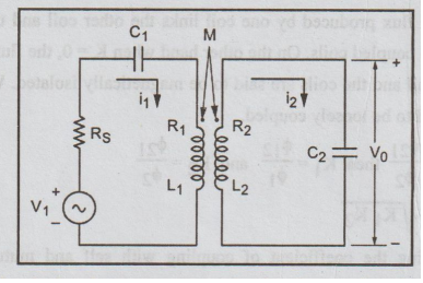
The double tuned circuits involve two resonant circuits. One on the primary side and other on the secondary side. On the primary side the resonant circuit consists of a coil with resistance R1 and inductance L1 in series with capacitor C1. The input voltage source V1 with source resistance RS is connected with the resonant circuit. On the secondary side the resonant circuit consists of coil 2 with resistance R2 and inductance L2 in series with capacitance C2. Both resonant circuits are inductively coupled with mutual inductance M.
If the coupled coefficient is K, then the mutual inductance
M = K√ L1L2
In analyzing the above circuit we assume that the primary and secondary circuits have the same resonant frequency given by
ωr = 1/√L1C1 = 1/√L2 C2
(OR)
15. (b) Derive the formula for mutual inductance in terms of coefficient of coupling and self inductance.
The coefficient of coupling can be defined for two coils linked by magnetic flux. It is a measure of flux linkages between two coils. The coefficient of coupling is defined as the function of the total produced by one coil linking another and it is denoted by 'K'.
Let ϕ1 =Flux produced by coil 1
ϕ2 = Flux produced by coil 2
ϕ12= Flux produced by coil 1 linking coil 2
ϕ21= Flux produced by coil 2 linking coil 1
Now coefficient of coupling K = ϕ12/ϕ1 = ϕ21 /ϕ2
When K = 1, all the flux produced by one coil links the other coil and the coils are said to be tightly coupled or closely coupled coils. On the other hand when K = 0, the flux produced by one coil does not link the other coil and the coils are said to be magnetically isolated. When the value of K is very low the coils are said to be loosely coupled.
When
ϕ12 / Φι ≠ ϕ21 / ϕ2 then K1 = ϕ12 / Φ1 K2 = ϕ21 / ϕշ
Now K = √K1 K2
An expression relating the coefficient of coupling with self and mutual inductance can be obtained as shown below.
On multiplying the equations
M12 × M21 = N2ϕ12 / i1 × N1ϕ21 / i2
From equations
M12 = M21 = M, ϕ12= K ϕ1 and ϕ2 = Kϕ2
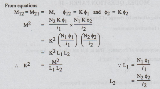
Now Coefficient of coupling, K = M / √L1 L2
Mutual inductance, M = K√ L1 L2
The equation can be used to find the coefficient of coupling in terms of self and mutual inductance. The equation can be used to find mutual inductance in terms of coefficient of coupling and self inductances.
Electric Circuit Analysis: Model Question and Answer : Tag: : Electric Circuit Analysis - Model Question and Answer - 1 PART B
Related Topics
Related Subjects

Electric Circuit Analysis
EE3251 2nd Semester 2021 Regulation | 2nd Semester EEE Dept 2021 Regulation