Electric Circuit Analysis: Model Question and Answer
Model Question Paper with Answer - 2 (PART B)
Electric Circuit Analysis
Electric Circuit Analysis: Model Question and Answer : Model Question Paper - II Part B
PART B-(5 × 16 = 80 MARKS)
11. (a) (i) Use nodal voltage
method and hence find the power dissipated in the 10 ohms resistor on the
circuit shown in figure. (8)
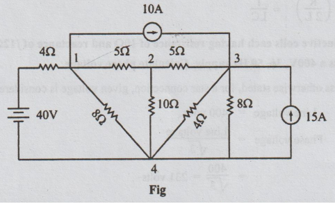
Solution:
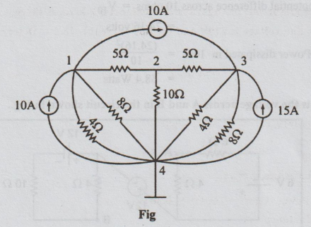
Taking
the node 4 as reference, and converting the voltage source into current source,
the above network is re-drawn as below:
The
power dissipated in 10 Ω =( V10)2/10 , (formula
is power = V2 /R)
V10
= V2 - V4 = V2-0 = V2
By
inspection, we get
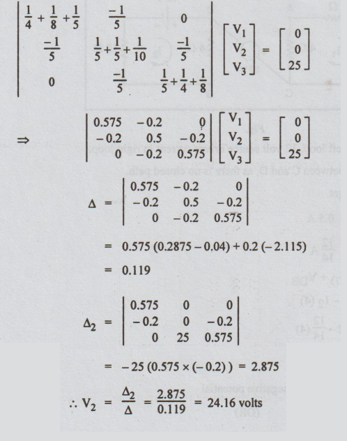
=
-25 (0.575 × (-0.2)) = 2.875
V2
= Δ2/ Δ = 2.875/ 0.119 = 24.16 volts
Therefore,
the potential difference across 10 ohms = V10
=
24.16 volts
Power
dissipated in 10 Ω = (24.16)2/10
=
58.4 Watts
11. (a) (ii) What is the voltage
across A and B in the circuit shown in Fig..
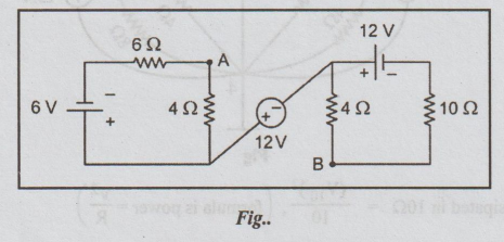
Solution:
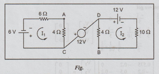
6V
source drives current in left loop, 12 volt source drives current in right
loop. There is no current flowing between C and D, as there is no closed path.
By
Ohm's law, applied, we get
I1
= 6 / 6 + 4 = 0.5 A
I2
= 12 / 4 + 10 = 12/14 A
VAB
= VAC + VCD + VDB
VAB
= I1 (4) – 12 - I2 (4)
=
0.5 (4) – 12 - 12
=
-13.43 volts
=
13.43 volts with B at negative potential
(OR)
11.(b) (i) In the network shown in
figure determine V2 such that the current in the 2 + j3 impedance is zero.
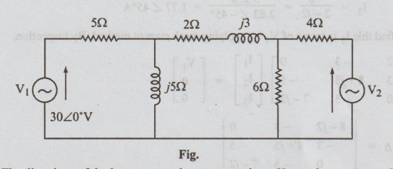
Solution:
The
directions of the loop currents here are not given. Hence, let us assume that
they are all clockwise. Since the current through (2 + j3) is given to be zero,
I2 = 0 => Δ2/ Δ = 0. Hence, the condition
Δ2
= 0. So, by inspection
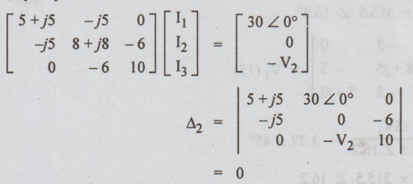
⇒ (5 + j5) (-6V2)-30
∠ 0° (-50 j) = 0
7.07
∠ 45 × (-6 V2) = - 1500 ∠ 90°
V2 = - 1500 ∠ 90° / -42.42 ∠
45°
=
35.36 ∠ 45°
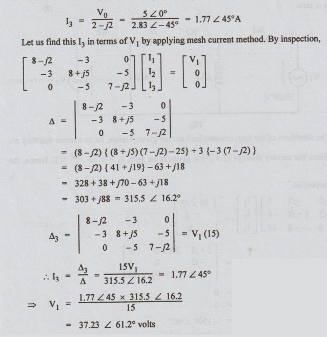
11 (b) (ii) In the network shown in
the figure the source V1 results in a voltage V0 across
the (2 - j2)Ω impedance. Find the source V1 which corresponds to V0=50°
volts. (8)
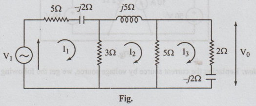
Solution:
Let
the loop currents be I1, I2 and I3.
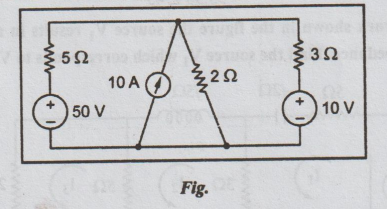
11. (b) Using source
transformation, replace the current source in the circuit shown below by a
voltage source and find the current delivered by the 50V voltage source. (8)
Solution:
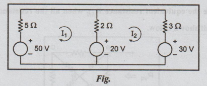
Replacing
the current source by voltage source, we get the following circuit.
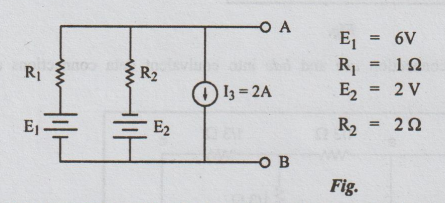
12. (a) (i) For the circuit shown
below obtain the equivalent current source between the terminals
Solution:
This
problem is a parallel combination of voltage and current sources.
Step
1: Converting the voltage sources into current sources
and re-drawing the circuit, the following figure is obtained.
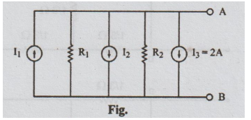
I1
= 6/1 = 6A; R1 =1 Ω; I2 = 2/2 = 1A; R2
=2 Ω
Step
2: The equivalent current source of the above circuit
is as shown below:
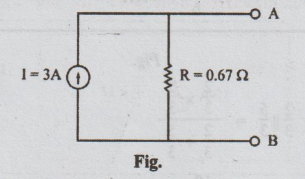
I
= I1 - I2 - I3 = 6-1-2 = 3A
R
= R1|| R2 = R1 R2 / R1 + R2
=
1 × 2 / 1+2 = 2/3 = 0.67 Ω
12. (a) (ii) Calculate the
equivalent resistance Rsh when all the resistance values are equal
to 1Ω for the circuit shown below. (8)
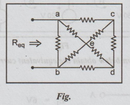
Solution:
Converting star connection ace and bde into equivalent data connections and
redrawing the circuit, we get
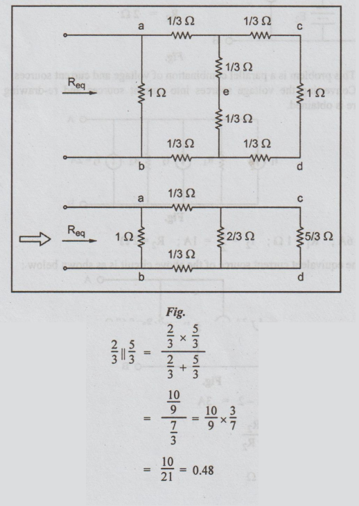
Then
the circuit becomes
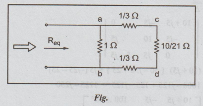
1/3 + 1/3 + 10/21 = 24/21 = 8/7
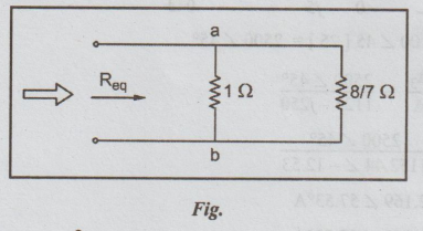
Req
= Rab = 1× 8/7 / 1 + 8/7 = 0.533 Ω
(OR)
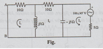
12. (b) (i) In the network shown in
the figure, the voltage source 100 ∠45°V
causes current Ix in the 5.2 branch. Find Ix and then verify the
reciprocity theorem for this circuit.
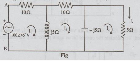
Solution:
Step 1: It is required to find the value of Ix.
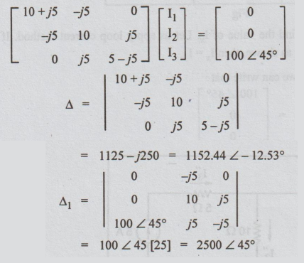
Let us apply loop current method. If the loop currents are taken to be I1,
I2 and I3 as shown, then Ix = I3.
For
the above circuit, by inspection, we can write that
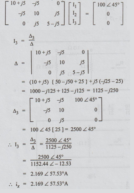
I3
=Δ3/Δ = 2500 ∠ 45°
/ 1125-j250
=
2500 ∠45o / 1152.44 ∠ -12.53
=
2.169 ∠ 57.53°A
ix=
2.169 ∠ 57. 53o A
Step
2: Now connect the voltage source in the branch in
which the current is Ix i.e., in 5Ω branch and connect an a.c.
ammeter in the branch where the voltage source was connected earlier as shown
below. If ammeter is not available, short the terminals A and B.
If
the current through AB is same as the value of Ix in the step 1, we
can say that the reciprocity theorem is verified. To calculate the current let
us again prefer loop current method to other methods. By inspection.
I1
= Δ1/Δ = 2500
∠ 45° / 1152.44 ∠ -12.53o
=2.169
∠ 57. 53o A
I1
= IAB = Ix
Hence
the reciprocity theorem is verified.
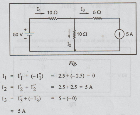
12. (b) (ii) Find the current
through various branches of the circuit shown below, by employing superposition
theorem. (8)
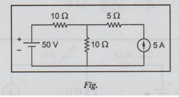
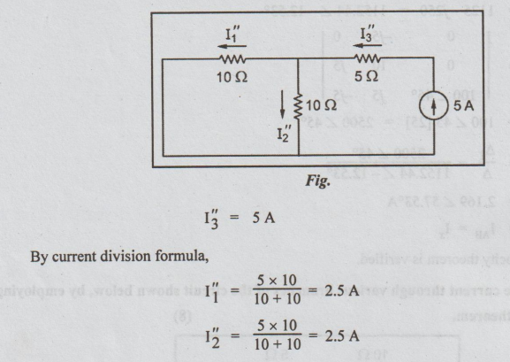
Step
1: Allow only voltage source to act. Open circuit the
current source.
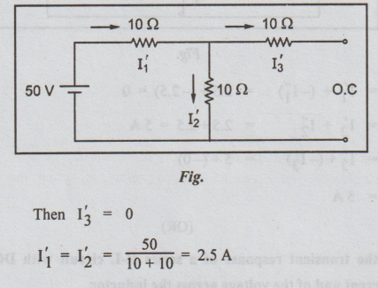
Step
2: Allow only current source to act. Short circuit the
voltage source.
Step
3:
(OR)
13. (a) (i) Derive the transient
response of a series R-L circuit with DC input. Sketch the variation of current
and of the voltage across the inductor.
(a) Case 1: (a) R-L Transients:
(Rise of current) (16)
Let
the R - L series combination be impressed upon the d.c. voltage E by closing
the switch K. Assume that the current through the inductor before closing the
switch is zero. Let K be closed at the instant t = 0.
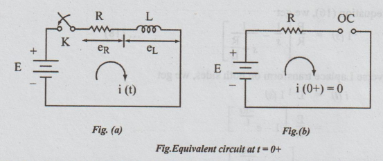
The
equivalent circuit at t = 0+ is shown in fig. The inductor is shown as open
circuit. Hence i (0-) = i(0+) = 0.
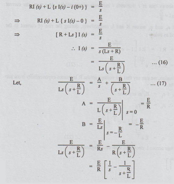
Applying
KVL to the circuit in fig. after t seconds of closing K,
we get, Ri+L di/dt = E .....(15)
Taking
Laplace Transformation on both sides, we get
Steady
current is the value of i(t) for t = ∞.
L/R
is called time constant of the RL circuit and is denoted by T.
Hence
equation (19) can be written as
I
= 1 [1-e-t/T]......... (20)
The
above equation shows that as t increases i increases exponentially. At t = ∞,
the current reaches steady state value I = E / R
The
transient voltage eR and eL across R and L respectively,
during the rise of current in the inductive can be expressed as below:
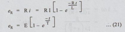
From
the above expression, we can say that the voltage across R increases
exponentially from zero to E, during rise of current.
By
KVL, eR + eL = E, at any time
eL
= E - eR
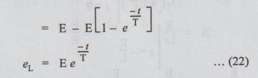
It
shows that the voltage across L decreases with time, exponentially
[
Note: eL = -L di / dt ]
The
variation of i(t) with time is graphically shown in fig. and that of e, and e,
is shown in fig. .
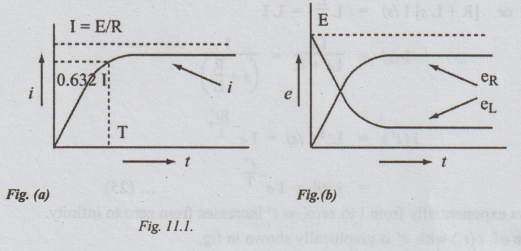
Definition of time constant T for
RL circuit
Substituting
T = t in equation (20), we get
i
= I (1 - e-1)
=
0.632 I
=
63.2% of I
Thus
the time constant of RL series circuit is defined as the period during which
the current rises to 63.2% of its final value (OR steady value).
(b) RL-Decaying Transients
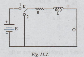
Assume
that the switch K is kept connected to position 1 for sufficiently longer
period. Then the current reaches steady state value given by I = E / R After
this instant, let the switch be moved from position 1 to position 2. Let this
instant be taken as t’ = 0. After t' seconds of closing the switch to position,
applying KVL,
Ri+
L di / dt' = 0 ....(23)
Taking
Laplace Transformation on both sides, we get
RI
(s) + L [SI (s)-i (0+)] = 0 .....(24)
Here
i (0+) = I = E / R
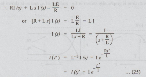
Thus
i decays exponentially from I to zero, as t' increases from zero to infinity.
The
variation of i (t') with t' is graphically shown in fig.
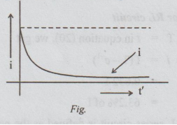
Decaying
current in an R-L circuit.
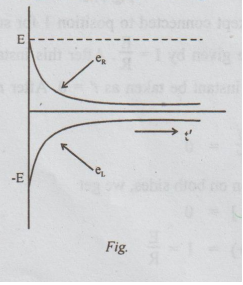
eR
= Ri = RI e-t/T
eR
= Ee-t/T ....(26)
eR
+ eL = 0
The
variatiom of eR and eL ith t’ is graphically shown in
fig.
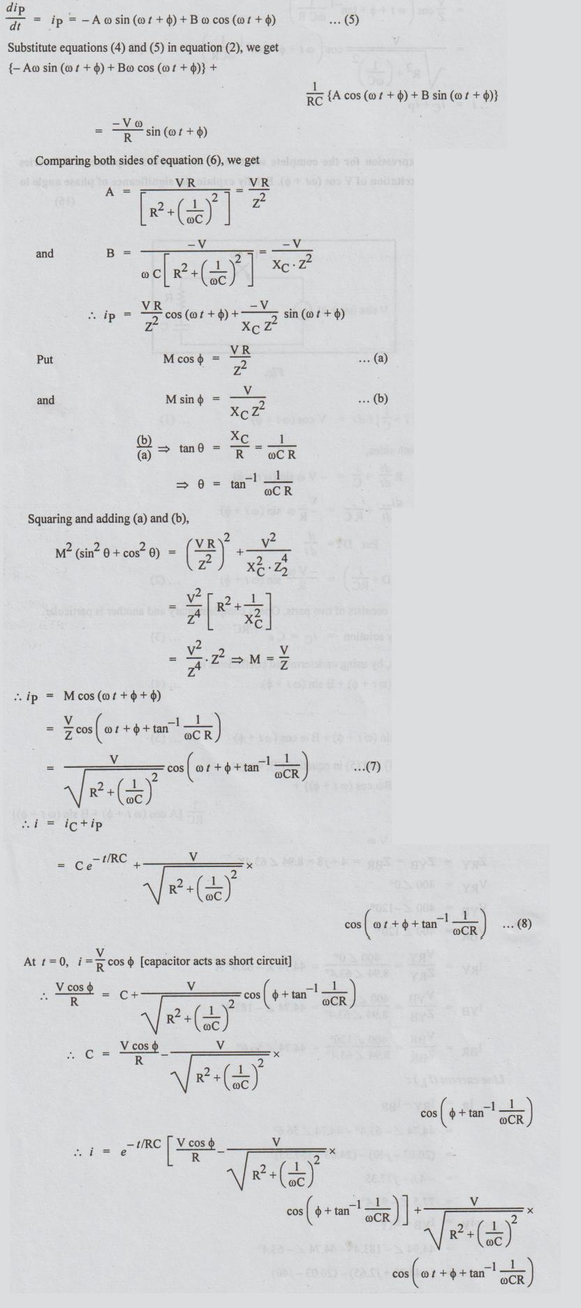
13. (b) Derive the expression for
the complete solution of the current response of RC series circuit with an
excitation of V cos (ωt + ϕ). Briefly explain the significance of phase angle
in the solution. (16)
Solution:
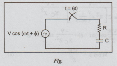
Apply
KVL to get
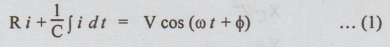
Differentiating
on both sides,
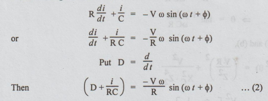
The
complete solution consists of two parts. One is complementary and another is
particular.
Complementary
solution = iC = C e - t/RC....(3)
The
particular solution, by using undetermined coefficients is
Ip
= A cos (ωt + ϕ )+ B sin (ωt + ϕ)...(4)
Differentiating
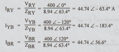
14. (a) (i) A 3-phase balanced
delta-connected load of (4+ j8) Ω is connected across a 400V, 3- phase supply.
Determine the phase currents and line currents. Assume the RYB phase sequence.
Also calculate the power drawn by the load. (16)
Solution:
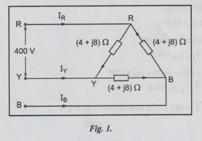
ZRY
= ZYB = ZBR=4+j8 = 8.94 ∠ 63.4°
VRY
= 400 ∠ 0°
VYB
= 400 ∠ -120°
VBR = 400 ∠
120°
Line current (IL):
IR
= IRY - IBR
=
44.74 ∠ -63.4° - 44.74 ∠ 56.6°
=
(20.03 - j40) - (24.63 +j37.35)
=
-4.6 - j77.35
=
77.5∠ -93.4°
IY
= IYB - IRY
=
44.94 ∠ -183.4°- 44.74 ∠ -63.4°
=
(-44.70+j2.65) - (20.03 -j40)
=
-64.73 + j42.16
=
77.5 2146.6
IB
= IBR - IYB
=
(24.63 + j37.35) - (-44.7 + j2.65)
=
69.33 + j34.7
=
77.5 ∠ 26.6° A
Total
power delivered to the load
P
= 3 Vph Iph cos ϕ
=
3 × 400 × 44.74 × cos 63.74°
or
P = √3 VL IL cos ϕ
=
√3 × 400 × 77.5 × cos 63.74° = 23754 W
(OR)
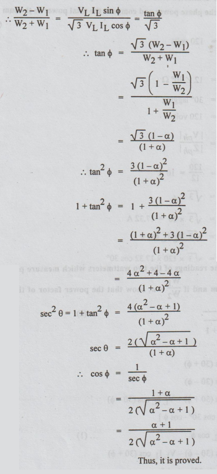
14. (b) (i) If W1 and W2 are the
readings of the two wattmeters which measure power in the three phase balanced
system and if W1/W2 = a, show that the power factor of
the circuit is given by cos ϕ = α + 1 / 2√ σ 2 - σ + 1 (8)
Solution:
W1
= VL IL cos (30 + ϕ)
W2
= VL IL cos (30 - ϕ)
W1
+ W2 = VL IL cos (30 + ϕ) + VL IL
cos (30 - ϕ)
=
VLIL [2 cos 30°. cos ϕ]
=
√3 VL IL Cos ϕ ....(1)
W2
- W1= VL IL cos (30 – ϕ ) - VL IL
cos (30 + ϕ )
=
VLIL [2 sin 30°. sin ϕ ]
W2-W1
= VL IL sin ϕ.....(2)
14. (b) (ii) Obtain the readings of
two wattmeters connected to a three-phase three-wire 120V system feeding a
balanced A-connected load with a load impedance of 12∠ 30° Ω. Assume either phase
sequence. Find the phase power and compare the total power to the sum of the
wattmeter readings. (8)
Solution:
VL
= 120 volts
Δ
connected load:
Load
impedance/phase = 12 ∠
30° Ω
ϕ
= 30° lagging
Vph
= VL = 120 volts
Phase current =
=
120/12 = 10 A
Line
current = IL = √3Iph
=
√ 3× 10 = 17.32 A
Total
power = √3 VL IL Cos ϕ
=
√3 × 120 × 17.32 cos 30°
=
3117.6 watts
Readings
of two wattmeters:
W1
= VL IL cos (30 + ϕ )
=
120 × 17.32 cos (30+30) = 1039.2
W2
= VL IL cos (30 -ϕ)
= 120 × 17.32 × cos (30o – 30o)
= 2078.4
W1+
W2 = 1039.2+2078.4
=
3117.6 watts
It is observed that sum of the two wattmeter readings is equal to the power calculated by the formula P =√3 VL IL cos ϕ.
15. (a) (i) Derive the relationship
between self inductance, mutual inductance and coefficient of coupling. (8)
Self Inductance
Consider
a circuit through which the current changes. So, the flux linking with the
circuit also changes. According to Faraday's law of induction an e.m.f. is
induced in the circuit. This e.m.f. is equal to rate of change of flux linkage.
i.e.,
e = N dϕ / dt... (1)
Also
e is proportional to time rate of change of current i.e., e ∞ di / dt
or e = L di / dt..... (2)
From
equations (1) and (2), we can write,
L
di / dt = N dϕ / dt....(3)
(or)
L = N dϕ / di ......(4)
If
the permeability is constant then, we can write that,
L = Nϕ / i .. (5)
L
is called self inductance of the circuit.
Definition
of L:
The
self inductance of a coil is defined as flux linkage in that coil per 1 ampere
current in the same coil. It is also defined as the weber turns per ampere
current in the coil. L is measured in Henry.
Here,
N = No. of turns of the coil
Φ
= Magnetic flux in webers
i
= current in amperes
[Note: (i) According to Lenz's law,
sign is to be given to the right hand side of the expressions shown in
equations (1) & (2).
(ii)
The terms N, o and i are confined to only one coil to define 'L']
Mutual Inductance
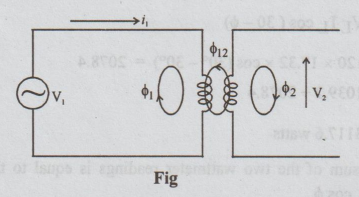
Consider
the circuit shown in fig. 8.1, the changing current i1 produces a
variable flux ϕ1 in the first coil. For the purpose of analysis, ϕ1
is divided into two components.
ϕ1
= ϕ11 + ϕ12.............(6)
Here
ϕ1 is the total flux established by i1, ϕ11 =
a part of ϕ1. It links with coil 1 only but not with coil 2.
ϕ12
= it is a part of ϕ1. It
links with both coils 2 and 1.
As,
the flux linking with coil 2 changes, an e.m.f. is induced in the coil ϕ2
and is given by
e2
= N2 dϕ12 / dt ... (7)
Also,
e2 is proportional to time rate of change of i,. It is because ϕ12
is produced by i1, therefore,
e2
= M di1 / dt......(8)
From
equations (7) and (8), we can write that,
M
= N2 dϕ12 / di1...(9)
If
the permeability is constant, the above equation becomes
M
= N2 ϕ12 / i1 ..................(10)
Suppose
that the second coil is connected to a voltage source. Let i2 be the
current flow and ϕ2 be the total flux.
ϕ2
= ϕ22 + ϕ21
Here,
ϕ21 is a part of ϕ2 and links with coil 1. Then, the
e.m.f. in the coil 1 = e1.
e1
= N1 dϕ21 / dt ... (11)
also
e1 = M di2 / dt... (12)
Hence
M di2/dt =N1 dϕ21 / dt
Hence
M = N1 ϕ21 / i2... (13)
In
equations (10 & 13) M is called mutual inductance.
Definition
of M
The
mutual inductance between 2 coils is defined as the weber turns in one coil per
ampere current in other coil. It is measured in henrys.
The
mutual inductance is also defined as the ability of one coil to produce e.m.f.
in other coil by induction when the current in the first changes.
Coefficient
of coupling (K) or coefficient of magnetic coupling (KM).
Consider
the fig. the fraction of the total flux produced by coil 1 linking coil 2 is
It
is called ϕ12 / ϕ1 coefficient of coupling. Thus
K
= ϕ12 / ϕ1 ....(14)
Also
K = ϕ21 / ϕ2... (15)
Multiplying
equations (10) & (13), we get
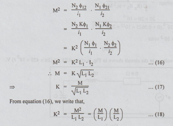
From
equation (16), we write that,
K2=
M2 /L1L2 = (M/L1) (M/L2)...(18)
From
the above expression, we can say that
M/L1
,M and M/L2 are in geometric progression.
Note:
(i) The values of K depends on spacing,
orientation of the coils and on the permeability of the medium.
(ii)
It is a non-negative number and is independent of the reference directions of
the currents.
(iii)
If the coils are at great distance apart, M is very small and hence K.
(iv)
For iron-core coupled circuits, K may be as high as 0.99.
(v)
For air-core coupled circuits, K varies between 0.4 and 0.8.
(vi)
The maximum value of K is 1. Hence Mmax = √L1 L2.
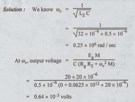
15. (a) (ii) In the single tuned
resonant circuit, the applied voltage in a primary coil Eg = 20
volts (assume Rg=0), R1=R2=5Ω L1=L2=32µH,
M=20 μH
C = (secondary side capacitance)
0.5 μF
Determine the resonant frequency
and the output voltage at this frequency.
Solution:
We
know ωr = 1/√L2 C
(OR)
15. (b) (i) The signal voltage in
the circuit shown in Fig. is e(t) = 0.01 sin (2π × 455 × 1031) V.
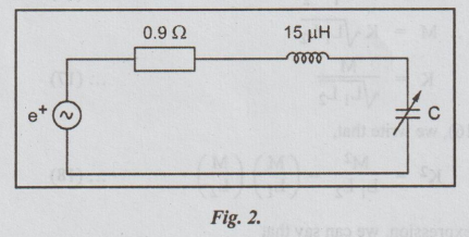
What should be the value of C in
order that the circuit would resonate at this signal frequency? At this
condition, find the values of I, VC, Q and bandwidth of the circuit.
(10)
Solution:
e
= 0.01 sin (2π × 455 × 103 t) volts
R
= 0.9 Ω
=
15 μH = 15 × 10-6 H
2π
f = 2π × 455 × 103
fr
= f = 455 × 103 cps
At resonance:
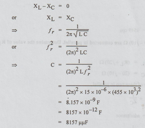
=
8.157 ×10⁻⁹ F
=
8157 × 10-12 F
=
8157 µµF
At
resonance:
I
= Im = E/R
E
=Em / √2 = 0.01/√2
=
7.07 × 10⁻³ volts
I
= E / R
=
7.07 × 10⁻³ volts
I
= E / R
=
7.07 ×10⁻³ / 0.9
=
7.86 × 10⁻³ A = 7.86 mA
VC
= IXC
= -7.86
× 10-3 (1/2πfC)
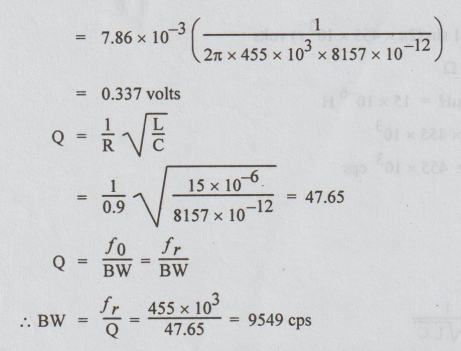
BW = fr
/ Q = 455 × 103 / 47.65 = 9549 cps
15. (b) (ii) (RL+j20) Ω and
(20-j10) are connected in parallel. Determine the value of RL for
resonance. (6)
Solution:
Let
ZL = (RL+ j20)Ω
ZC
= (20 – j10) Ω
Let
ZT be the total impedance of these two in parallel.
Then,
1/ZT = 1/ZL = 1/ZC
1/Z
= Y = admittance
YT = 1/ZL + 1/ZC
=
1/RL + j20 + 1/(20-j10)
After
rationalising,
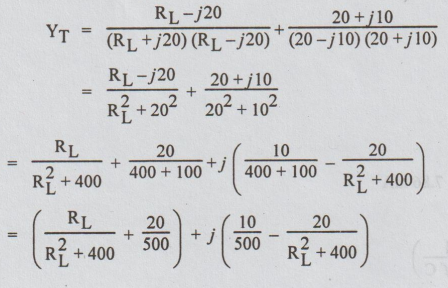
At
resonance, the reactive part of YT=0
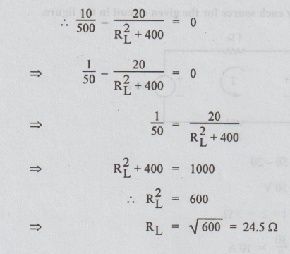
RL2
+ 400 = 1000
RL2
= 600
RL
= √600 = 24.5 Ω
Electric Circuit Analysis: Model Question and Answer : Tag: : Electric Circuit Analysis - Model Question Paper with Answer - 2 (PART B)
Related Topics
Related Subjects

Electric Circuit Analysis
EE3251 2nd Semester 2021 Regulation | 2nd Semester EEE Dept 2021 Regulation