Electric Circuit Analysis: Model Question and Answer
Model Question Paper with Answer - 3 (PART B)
Electric Circuit Analysis
Electric Circuit Analysis: Model Question and Answer : Model Question Paper - III Part B
PART-B (5 × 16 = 80
marks)
11.
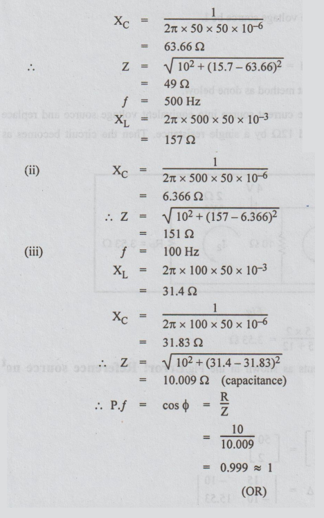
(a) A voltage source of 10Ω with a resistance of 1052, an inductance of 50 mH
and a capacitor of 50 μF are connected in series. Calculate the impedance when
the frequency is (i) 50 Hz, (ii) 500 Hz, (iii) Power factor at 100 Hz.
Ans:
Z
= √ R2 + (XL-XC)2
XL
=2π fL
XC
= 1 / ωC = 1/ 2π fс
f
= 50 Hz
XL
= 2π × 50 × 50 × 10-3
=
15.7 Ω
(OR)
11. (b) Calculate the power
delivered by the voltage source of Fig.
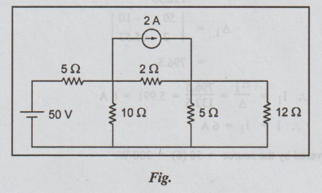
Solution:
Let the current from the voltage source be I.
Then
power delivered by the source
=
V I = 50I
To
find I, we shall apply loop current method as done below.
For
more simplification, convert the current source into equivalent voltage source
and replace the parallel combination of 50 Ω and 12 Ω by a single resistance.
Then the circuit becomes as below.
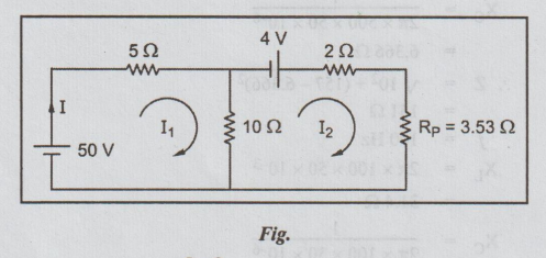
RP
= 5 × 2 / 5 + 12 = 3.53 Ω
Let
I1 and I2 be the loop currents as shown in the Fig. Error! Reference source not found..
Then
by inspection
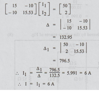
I1=
Δ1 / Δ = 796.5 /132.5 == 5.991 = 6 A
I
= I1 = 6 A
Power
delivered by the source = 50 (6) = 300 W
12.
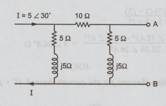
(a) Find the Thevenin's equivalent circuit for the network shown in the figure
at the terminals AB.
Ans:
Step
1: Thevenin's equivalent between A and B is
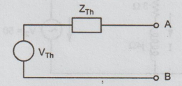
Step
2: To find VTh or Voc: Let the
current through 10 Ω be I1.
Voc
= VAB = VTh
=
I1 × (5 + j5)
I
is divided into 2 parallel paths of impedances ( 5+ j5) and 10 + 5+ j5 = 15 + j5.
Current
through 15 + j5 = I1
By
division of current formula,
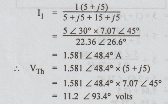
Step
3: To calculate ZTh:
From
the given circuit, kill the current I to obtain the following figure.
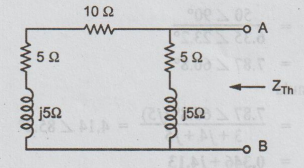
ZTh
=ZAB = (10 + 5 + j5) || (5 + j5)
= (15 + j5) (5 + j5) / 15 + j5 + 5 + j5
= 15.81
∠ 18.43° × 7.07 ∠ 45° / 22.36 ∠ 26.6° = 5 ∠
36.8o Ω
(OR)
12.
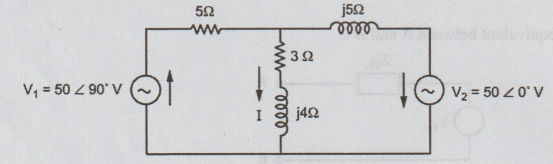
(b) Verify superposition theorem for the current through (3 + j4) branch as
shown in the figure.
Ans
:
Step
1: Let only V1 to act. V2 is short
circuited.
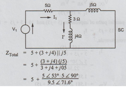
=
5 + 2.63 ∠ 71.4°
=
5.84 + j2.5
=
6.35 ∠ 23.2°
I1
= V1 / ZT
=
50 ∠ 90° / 6.35 ∠ 23.2°
=
7.87 ∠ 66.8°
By
current division formula
I'
= 7.87 ∠ 66.8° (j5) / 3 + j4 + j5 = 4.14 ∠
85.2°
= 0.346 + j 4.13
Step
2: Let V2 source be acting, short circuit V1.
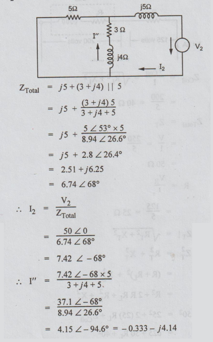
By
superposition theorem,
I = I' - I"
=
0.679 + j8.27
=
8.3 ∠ 85° A
13.
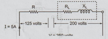
(a) A current of 5 A flows through a non-inductive resistance in series with a
coil, when supplied at 250 V, 50 Hz. If the voltage across the resistance is
125 V and that across the coil is 200 V, calculate
(i)
Impedance, resistance and reactance of the coil.
(ii)
Total power absorbed by the coil.
(iii)
Total power. Draw phasor diagram.
Ans
:
ZCoil
= VCoil / I = √RL2+XL2
=
200/5 = 40 Ω
ZTotal
= ZT
=
V/I = 250.5
=
50 Ω
R
= VR /I
=125/5
= 25Ω
But,
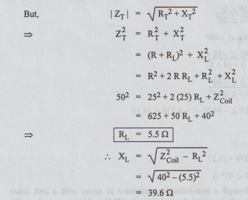
Power
absorbed by coil = I2RL
=
(5)2 × 5.5
=
138 W
Total
p.f. = cos ϕ = RT/ZT
=
25 + 5.5 / 50 = 0.61 lag
Total
power = VI cos ϕ
=
250 × 5 × 0.61
=
763 W
Phasor
diagram
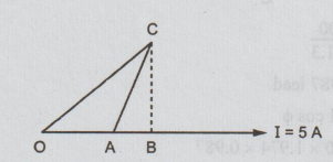
OA
= VR = 125
AB
=VRL
BC
= VXL
AC
=VCoil = 200 V
OC
= V = 250 V
(ii)
A series circuit has R = 100Ω ; L = 50 mH and C = 100 μF and is supplied with
200 V, 50 Hz. Find
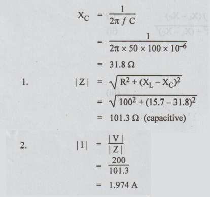
1.
The impedance
2.
The current
3.
Power factor
4.
The power
5.
Voltage drops across each element
Ans:
Please refer to Page 3.31 for similar type.
XL
= 2π ƒ L
=
2 × 50 × 50 × 10-3
=
15.7 Ω
XL
= 1 / 2π ƒ С
3.
Power factor = cos ϕ = R/Z
=
100/101.3
=
0.987 lead
4.Power
= VI cos ϕ
=
200 × 1.974 × 0.987
=
390 W
5.
VR= I R
=
1.974 × 100
=
197.4 volts
VL
= I XL
=1.974
× 15.7
=
31 volts
VC
= I XC
=
1.974 × 31.8
=
62.8 volts
(OR)
13.
(b) Show that the resonant frequency of a series RLC circuit is f,1/2π
√LC
expression
for Q factor.
Series Resonance
In
a R-L-C series circuit, when the current is in phase with the applied voltage,
the circuit is said to be in resonance. Then, phase angle is zero and hence
power factor is unity. The circuit acts as purely resistive
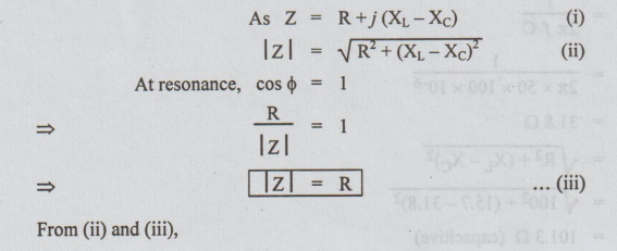
XL
- XC = 0
XL
= XC
ωr
L = 1/ ωrC
ωr
= 1/ √LC
fr
=
ωr / 2π
fr
= 1/ 2π √LC
fr
or f0 is called resonance frequency. At resonance, in a series
circuit the following main effects are to be observed.
(b)
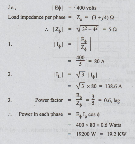
(ii) A 3 phase delta connected RYB system with an effective voltage of 400 V
has a balanced load with impedance (3+j4) Ω Calculate
1.Phase
current
2.Line
current
3.
Power in each phase
Ans:
Please refer to Page 6.16 for same type.
Phase
voltage = Line voltage = 400 volts
(For
delta system)
14
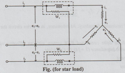
(a). Draw the circuit of 3 phase balanced star connected load with wattmeters
for power measurement and also prove that two wattmeters are sufficient to
measure 3 phase power.
Three Phase Power Measurement
Two-Watt Meter Method
This
method is applied usually for measuring the electrical power in 3-phase, 3-wire
circuit. The load may be balanced or unbalanced. It may be connected either in
delta or star.
The
current coils of 2 wattmeters are inserted in two of the lines and voltage coil
of each wattmeter is connected from its own current coil to the line in which
no wattmeter has been connected. The connections of wattmeters in this method
are shown in Fig.
Let
e1, e2 and e3 be the voltages of the three
loads at particular instant and i1, i2 and i3
be the currents of the three loads i.e., these voltages and currents are called
instantaneous values. Hence, the power at the instant under consideration is
equal to the sum of their products, regardless of power factor
i.e.,
Instantaneous power = P= e1i1 + e2i2
+ e3i3 ... (1)
Case (1) Load - Star connected
Since
all the three-phases meet at a star point, application of KCL yields
i1+i2+
i3 = 0
or
i3 = - (i1+i2)
Substituting
i3 = - (i1 + i2) in expression (1) we get
p
= e1i1 + e2i2 - e3(i1
+i2)
=
i1 (e1 - e3) + i2 (e2 -
e3)
Here
i1 = the instantaneous current flowing through the current coil of
wattmeter. (e1-e3)= the instantaneous potential difference
across voltage coil of wattmeter 1.
Therefore
i1 (e1 - e3)= w1. w1 is the
instantaneous power measured by wattmeter 1.
i2
= The instantaneous currents flowing through the current coil of wattmeter 2.
(e2 - e3) = instantaneous potential difference across the
voltage coil of wattmeter 2.
i2
(e2 - e3) = w2. w2 is the
instantaneous power measured by watt meter 2.
Hence
p = w1 + w2 or total average power = P = W1 + W2.
Hence,
the algebraic sum of readings of the two wattmeters gives the total power in
the 3-phase, 3- wire star connected load. It is valid for both balanced and unbalanced
loads.
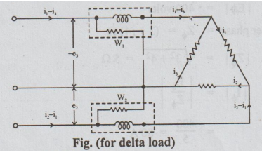
Case (2) Load - delta connected
In
delta connected system, the 3-phases form a close loop. According to KVL,
e1+e2+
e3 = 0
Or
e1 = - (e2+ e3)
From
equation (1), p = eii1 + e2i2 + e3i3
=
- (e2+ е3) i1 + е2i2 + e3i3
=
-e3 (i1 - i3) + e2 (i2 -
i1)
-
e3 is the instantaneous p.d. across the voltage coil of wattmeter 1.
(i1
- i3) the current flowing through wattmeter 1. So, first wattmeter
reads - e3 (i1- i3). Similarly, the second
wattmeter reads e2 (i2 - i1).
Hence,
the total instantaneous power = p = w1 + w2 and the total
average power = P = W1 + W2.
Thus,
the algebraic sum of the readings of the two wattmeters gives the total power
of the circuit. It is true for both balanced and unbalanced loads and for star
as well as delta connected systems.
(OR)
14. (b) Derive the formula for
total power consumed in unbalanced Y connected load.
Let
us assume a phase sequence of RYB. Let the reference phases be  .
The three wire three phase star connected unbalanced load with conventional
polarity of voltages and direction of currents is shown in Fig.
.
The three wire three phase star connected unbalanced load with conventional
polarity of voltages and direction of currents is shown in Fig.
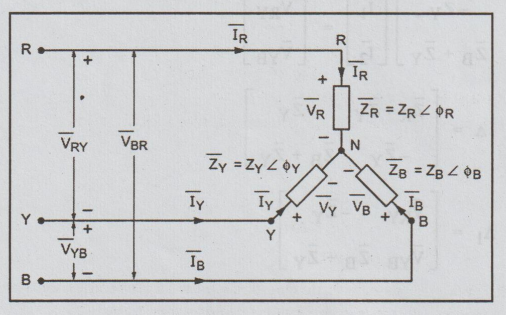
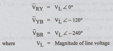
The
line voltages of the supply source for RYB sequence are,
In
unbalanced star connected load, it will be easier to solve, the line currents
by assuming two sources, across the lines whose values are equal to
corresponding line voltages. Consider the circuit in Fig. in which a voltage
source of value ![]() is connected across lines R and Y
and a voltage source of value
is connected across lines R and Y
and a voltage source of value ![]() is connected
across Y and B.
is connected
across Y and B.
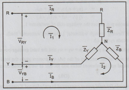
The
circuit of Fig. has two meshes, hence we can assume two mesh currents  as shown in the Fig. The mesh basis matrix equation is
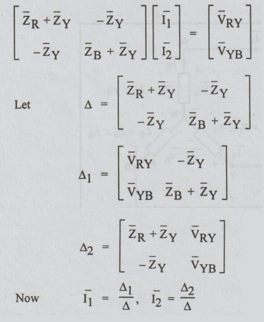
From
the mesh currents the line currents can be obtained
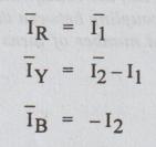
In
star connected load the phase currents are same as that of the line currents.
Therefore the phase and line currents in the polar form can be written as
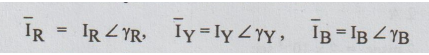
where 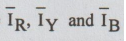 are the magnitude of line and phase
currents and ɤR,
ɤY, and ɤB are phase angle of line and phase
currents with respect to reference phasor.
are the magnitude of line and phase
currents and ɤR,
ɤY, and ɤB are phase angle of line and phase
currents with respect to reference phasor.
Now
the phase voltages are given by the product of phase current and phase
impedance. Therefore the phase voltages are,
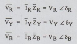
where
VR, VY and VB are magnitude of phase voltages
and δR, δY and δB are phase angle of phase
voltages with respect to reference phasor.
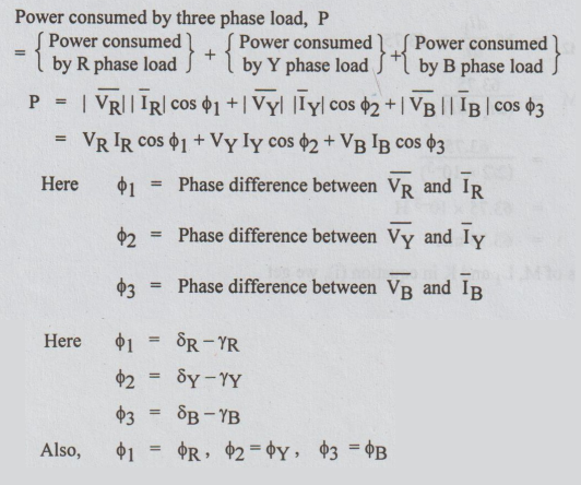
Power
consumed by three phase load, P
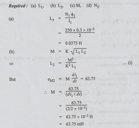
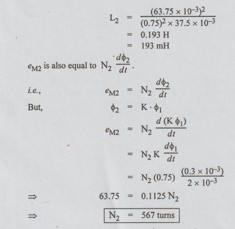
15. (a) The number of turns in a
coil is 250. When a current of 2 A flows in this coil, the flux in the coil is
0.3 mwb. When this current is reduced to zero in 2 ms, the voltage induced in a
coil lying in the vicinity of coil is 63.75 volts. If the coefficient of
coupling between the coils is 0.75, find self-inductance of the two coils,
mutual inductance and number of turns in the second coil.
Ans:
Data:
N1
= 250
I1
= 2 A
ϕ1
= 0.3 mwb = 0.3 × 10⁻³ wb
di1=
2 A
dt
= 2 msec = 2 × 10⁻³ sec
eM2
= 63.75 volts
K
= 0.75
Required:
(a) L1 (b)L2 (c) M, (d) N2.
Substituting
these values of M, L1 and K in equation (i), we get
(OR)
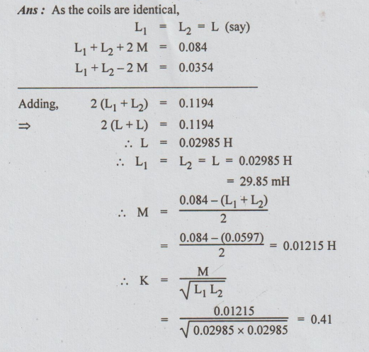
15.
(b) Two identical coupled coils in series has an equivalent inductance values
of 0.084 H and 0.0354 H. Find the values of L1, L2, M and
K.
Ans:
As the coils are identical,
L1
= L2 = L (say)
L1
+ L2 + 2 M = 0.084
L1
+ L2 - 2 M = 0.0354
Adding,
2 (L1+ L2 ) = 0.1194
2
(L + L) = 0.1194
L = 0.02985 H
.L1
=L2 = L = 0.02985 H
=
29.85 mH
Electric Circuit Analysis: Model Question and Answer : Tag: : Electric Circuit Analysis - Model Question Paper with Answer - 3 (PART B)
Related Topics
Related Subjects

Electric Circuit Analysis
EE3251 2nd Semester 2021 Regulation | 2nd Semester EEE Dept 2021 Regulation