Electrical Machines: Unit III: a. D.C. Motors
Necessity of Starter, Three Point, Four Point Starter
Working Principle, Disadvantage | D.C. Motors
• All the d.c. motors are basically self starting motors. Whenever the armature and the field winding of a d.c. motor receives supply, motoring action takes place. So d.c. motors do not require any additional device to start it. The device to be used as a starter conveys a wrong meaning.
Necessity
of Starter
AUMay-03, 10, 15 Dec.-03, 05,06,
07, 09, 10, 12,13,15, 17
•
All the d.c. motors are basically self starting motors. Whenever the armature
and the field winding of a d.c. motor receives supply, motoring action takes
place. So d.c. motors do not require any additional device to start it. The
device to be used as a starter conveys a wrong meaning.
Key Point:
So starter is not required to start a d.c. motor but it enables us to start the
motor in a desired, safe way.
•
Now at the starting instant the speed of the motor is zero, (N= 0). As speed is
zero, there cannot be any back e.m.f. as Eb ∝N and N is zero at
start.
Eb
at start = 0
The
voltage equation of a d.c. motor is,
V
= Eb + la Ra
So
at start,V = Ia Ra As Eb = 0
Ia
= V / Ra .............. At start
Key Point:
Generally motor is switched on with normal voltage and as armature resistance
is very small, the armature current at start is very high.
•
Consider a motor having full load input power as 8000 watts. The motor rated
voltage be 250 V and armature resistance is 0.5 Ω.
• Then at start, Eb
= 0 and motor is operated at 250 V supply, so
Ia
= V /Ra = 250 / 0.5 = 500 A
While
its full load current can be calculated as,
IFull
load = Power input on full load / Supply voltage
= 8000 / 250=32 A
•
So at start, motor is showing a tendency to draw an armature current which is
15 to 20 times more than the full load current.
•
Such high current drawn by the armature at start is highly objectionable for
the following reasons:
1.
In a constant voltage system, such high inrush of current may cause tremendous
line voltage fluctuations. This may affect the performance of the other
equipments connected to the same line.
2. Such excessively high armature current,
blows out the fuses.
3.
If motor fails to start due to some problems with the field winding, then a large armature
current flowing for a longer time may burn the insulation of the armature
winding.
4.
As the starting armature current is 10 to 15 times more than the full load
current, the torque developed which is proportional to the Ia will
also be 10 to 15 times, assuming shunt motor operation. So due to such high
torque, the shaft and other accessories are thus be subjected to large
mechanical stresses. These stresses may cause permanent mechanical damage to
the motor.
• To restrict this high
starting armature current, a variable resistance is connected in series with
the armature at start. This resistance called starter or a starting resistance.
So starter is basically a current limiting device. In the beginning the entire resistance
is in the series with the armature and then gradually cut-off as motor gathers
speed, producing the back e.m.f. The basic arrangement is Fig. 4.17.1

• In addition to the
starting resistance, there are some protective devices provided in a starter.
There are wo types of starters used for d.c. shunt motors. a) Three point
starter b) Four point starter
1. Three Point Starter
The
Fig. 4.17.2 shows this type of starter.
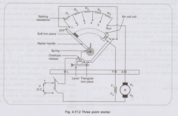
The
starter is basically a variable resistance, divided nto number of sections. The
contact points of these ections are called studs and brought out separately
hown as OFF, 1, 2, upto RUN. There are three nain points of this starter :
1.
'L' → Line terminal to be connected to positive of supply.
2.
'A' → To be connected to the armature winding.
3.
'F' → To be connected to the field winding.
• Point 'L' is further
connected to an electromagnet called overload release (OLR). The second end of
'OLR' is connected to a point where handle of the starter is pivoted. This
handle is free to move from its other side against the force of the spring.
This spring brings back the handle to the OFF position under the influence of
its own force. Another parallel path is derived from the stud '1', given to the
another electromagnet called No Volt Coil (NVC). The NVC is further connected
to terminal 'F'. The starting resistance is entirely in series with the
armature. The OLR and NVC are the two protecting devices of the starter.
Operation:
•
Initially the handle is in the OFF position. The d.c. supply to the motor is
switched on. Then handle is slowly moved against the spring force to make a
contact with stud no. 1. At this point, field winding gets supply through the
parallel path provided to starting resistance, through NVC. While entire
starting resistance comes in series with the armature and armature current
which is high at start, gets limited. As the handle is moved further, it goes
on making contact with studs 2, 3, 4 etc., cutting out the starting resistance
gradually from the armature circuit. Finally when the starter handle is in
'RUN' position, the entire starting resistance gets removed from the armature
circuit and motor starts operating with normal speed. The handle is moved
manually, and the obvious question is how handle will remain in the 'RUN'
position, as long as motor is running?
• Let us see the action
of NVC which will give the answer to this question along with some other
functions of NVC.
a. Functions of No Volt Coil
1.
The supply to the field winding is derived through NVC. So when field current
flows, it magnetises the NVC. When the handle is in the 'RUN' position, soft
iron piece connected to the handle gets attracted by the magnetic force
produced by NVC. Design of NVC is such that it holds the handle in 'RUN'
position against the force of the spring as long as supply to the motor is
proper. Thus NVC holds the handle in the 'RUN' position and hence also called
hold on coil.
2.
Whenever there is supply failure or if field circuit is broken, the current
through NVC gets affected. It looses its magnetism and hence not in a position
to keep the soft iron piece on the Jo handle, attracted. Under the spring
force, handle comes back to OFF position, switching off the a motor. So due to
the combination of NVC and the spring, the starter handle always comes back to
OFF position whenever there is any supply problem. The entire starting
resistance comes back in series with the armature when attempt is made to start
the motor everytime. This prevents the damage of the motor caused due to
accidental starting.
3.
NVC performs the similar action under low voltage conditions and protects the
motor from such dangerous supply conditions as well.
b. Action of Overload Release
•
The current through the motor is taken through the OLR, an electromagnet. Under
overload condition, high current is drawn by the motor from the supply which
passes through OLR. Below this magnet, there is an arm which is fixed at its
fulcrum and normally resting in horizontal position. Under overloading, high
current though OLR produces enough force of attraction to attract the a arm
upwards. Normally magnet is so designed that upto a full load value of current,
the force of attraction produced is just enough to balance the gravitational
force of the arm and hence not lifting it up. At the end of this arm, there is
a triangular iron piece fitted. When the arm is pulled upwards the triangular
piece touches to the two points which are connected to the two ends of NVC.
This shorts the NVC and voltage across NVC becomes zero due to which NVC looses
its magnetism. So under the spring force, handle comes back to the OFF
position, disconnecting the motor from the supply. Thus motor gets saved from
the overload conditions.
• In this starter, it can
be observed that as handle is moved from different studs one by one, the part
of the starting resistance which gets removed from the armature circuit compared
to the field winding resistance, this hardly affects the field winding
performance. But this addition of the resistance in the field circuit can be
avoided by providing a brass arc or copper arc connected just below the stud,
the end of which is connected to NVC, as shown in the Fig. 4.17.3.

The handle moves over this arc, supplying the
field current directly bypassing the starting resistance. When such an arc is
provided, the connection used earlier to supply field winding, is removed.
c. Disadvantage
• In this starter, the
NVC and the field winding are in series. So while controlling the speed of the
motor above rated, field current is reduced by adding an extra resistance in
series with the field winding. Due to this, the current through NVC also
reduces. Due to this, magnetism produced by NVC also reduces. This may release
the handle from its RUN position switching off the motor. To avoid the
dependency of NVC and the field winding, four point starter is used, in which
NVC and the field winding are connected in parallel.
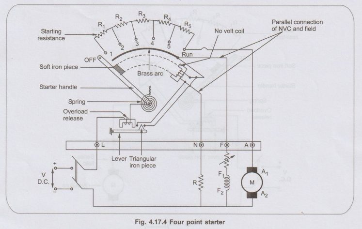
2. Four Point Starter
• The basic difference
between three point and four point starter is the connection of NVC. In three
point, NVC is in series with the field winding while in four point starter NVC
is connected independently across the supply through the fourth terminal called
'N' in addition to the 'L', 'F' and 'A'.
•
Hence any change in the field current does not affect the performance of the
NVC. Thus it is ensured that NVC always produce a force which is enough to hold
the handle in 'RUN' position, against force of the spring, under all the
operating conditions. Such a current is adjusted through NVC with the help of
fixed resistance R connected in series with the NVC using fourth point 'N' as
shown in Fig. 4.17.4.
a. Disadvantage
The
only limitation of the four point starter is, it does not provide high speed
protection to the motor. If under running condition, field gets opened, the
field current reduces to zero. But there is some residual flux present and N ∞ 1
/ ϕ the motor tries to run with dangerously high speed. This is called high
speeding action of the motor. In three point starter as NVC is in series with
the field, under such field failure, NVC releases handle to the OFF position.
But in four point starter NVC is connected directly across the supply and its
current is maintained irrespective of the current through the field winding.
Hence it always maintains handle in the RUN position, as long as supply is
there. And thus it does not protect the motor from field failure conditions
which result into the high speeding of the motor.
Review Questions
1. Give the reason of
using starters in d.c motors.
AU Dec.-10, May-15,
Marks 3
2. With neat sketch,
explain the function of 3 point starter.
AU: May-03, 10, 15,
Dec.-03, 06, 07, 09, 10, 13, 17, Marks 8
3. Explain with neat
sketch the function of no volt release and overload release in 3 point d.c.
motor no blow o starter.
AU: Dec.-05, Marks 8
4. Why starters are
necessary? Explain in detail the construction and working operation of 4 point starter.
AU: Dec.-15, Marks 16
5. Draw and explain
the operation of four point starter.
AU: Dec.-12, Marks 16
6. Why starting
current is high at the moment of starting a DC motor? Explain the method of
limiting the starting current in DC motors.
AU: May-15, Marks 6
Electrical Machines: Unit III: a. D.C. Motors : Tag: : Working Principle, Disadvantage | D.C. Motors - Necessity of Starter, Three Point, Four Point Starter
Related Topics
Related Subjects

Electrical Machines I
EE3303 EM 1 3rd Semester EEE Dept | 2021 Regulation | 3rd Semester EEE Dept 2021 Regulation