Electrical Machines: Unit IV: Single Phase Transformer
Open Circuit and Short Circuit Tests
Single Phase Transformer
The efficiency and regulation of a transformer on any load condition and at any power factor condition can be predetermined by indirect loading method.
Open
Circuit and Short Circuit Tests
AU: Dec.-06,07,08,10,15,16, 19,
May-08,10,11,12,13,16,17, Nov.-06, Oct.-02
•
The efficiency and regulation of a transformer on any load condition and at any
power factor condition can be predetermined by indirect loading method. In this
method, the actual load is not used on transformer. But the equivalent circuit parameters
of a transformer are determined by conducting two tests on a transformer which
are,
1.
Open Circuit Test (O.C. Test)
2.
Short Circuit Test (S.C. Test)
Key Point:
The parameters calculated from these results are effective in determining the
regulation and efficiency of a transformer at any load and power factor
condition, without actually loading the transformer.
•
The advantage of this method is that without much power loss the tests can be
performed and results can be obtained. Let us discuss in detail how to perform
these tests and how to use the results to calculate equivalent circuit
parameters.
1. Open Circuit Test (O.C. Test)
•
The experimental circuit to conduct O.C. test is shown in the Fig. 6.18.1.
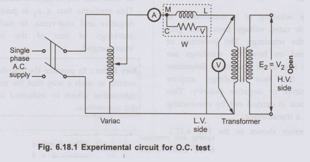
•
The transformer primary is connected to a.c. supply through ammeter, wattmeter
and variac. The secondary of transformer is kept open. Usually low voltage side
is used as primary and high voltage side as secondary to conduct O.C. test.
•
The primary is excited by rated voltage, which is adjusted precisely with the
help of a variac. The wattmeter measures input power. The ammeter measures
input current. The voltmeter gives the value of rated primary voltage applied
at rated frequency.
•
Sometimes a voltmeter may be connected across secondary to measure secondary
voltage which is V2 = E2 when primary is supplied with
rated voltage. As voltmeter resistance is very high, though voltmeter is
connected, secondary is treated to be open circuit as voltmeter current is
always negligibly small.
•
When the primary voltage is adjusted to its rated value with the help of
variac, readings of ammeter and wattmeter are to be recorded.
The
observation table is as follows
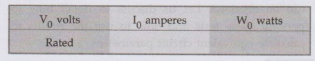
V0
= Rated voltage, W0 = Input power, I0 = Input current =
No load current
•
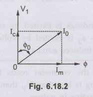
As transformer secondary is open, it is on no load. So current drawn by the
primary is no load current I0. The two components of this no load
current are,
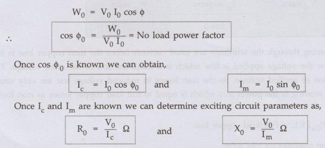
Im
= I0 sin ϕ0, Ic = I0 cos ϕ0
Where
cos ϕ0 = No load power factor
And
hence power input can be written as,
W0
= V0 I0 cos ϕ0
The
phasor diagram is shown in the Fig. 6.18.2.
•
As secondary is open, I2 = 0. Thus its reflected current on primary
is also zero. So we have primary current I1 = I0. The
transformer no load current is always very small, hardly 2 to 4 % of its full
load value. As I2 = 0, secondary copper losses are zero. And I1
= I0 is very low hence copper losses on primary are also very very
low. Thus the total copper losses in O.C. test are negligibly small. As against
this the input voltage is rated at rated frequency hence flux density in the
core is at its maximum value. Hence iron losses are at rated voltage. As output
power is zero and copper losses are very low, the total input power is used to
supply iron losses. This power is measured by the wattmeter i.e. W0.
Hence the wattmeter in O.C. test gives iron losses which remain constant for
all the loads.
W0
= Pi = Iron losses
Calculations:
We know that,
Key Point:
The no load power factor cos 'ϕ0 is very low hence wattmeter used
must be low power factor type otherwise there might be error in the results. If
the meters are connected on secondary and primary is kept open then from O.C.
test we get R'0 and X'0 and with which we can obtain Ro
and X0 and knowing the transformation ratio K.
2. Short Circuit Test (S.C. Test)
•
In this test, primary is connected to a.c. supply through variac, ammeter and
voltmeter as shown in the Fig. 6.18.2.
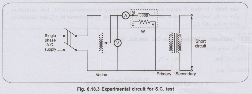
•
The secondary is short circuited with the help of thick copper wire or solid
link. As high voltage side is always low current side, it is convenient to
connect high voltage side to supply and shorting the low voltage side.
•
As secondary is shorted, its resistance is very very small and on rated voltage
it may draw very large current. Such large current can cause overheating and
burning of the transformer. To limit this short circuit current, primary is
supplied with low voltage which is just enough to cause rated current to flow
through primary which can be observed on an ammeter. The low voltage can be
adjusted with the help of variac. Hence this test is also called low voltage
test or reduced voltage test. The wattmeter reading as well as voltmeter,
ammeter readings are recorded. The observation table is as follows,
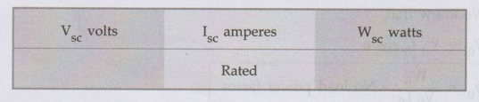
• Now
the currents flowing through the windings are rated currents hence the total
copper loss is full load copper loss. Now the voltage applied is low which is a
small fraction of the rated voltage. The iron losses are function of applied
voltage. So the iron losses in reduced voltage test are very small. Hence the
wattmeter reading is the power loss which is equal to full load copper losses
as iron losses are very low.
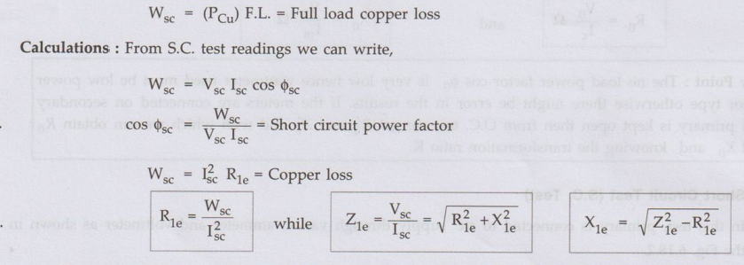
•
Thus we get the equivalent circuit parameters R1e X1e and
Z1e. Knowing the transformation ratio K, the equivalent circuit
parameters referred to secondary also can be obtained.
•
Important note: If the transformer
is step up transformer, its primary is L.V. while secondary is H.V. winding. In
S.C. test, supply is given to H.V. winding and L.V. is shorted. In such case we
connect meters on H.V. side which is transformer secondary though for S.C. test
purpose H.V. side acts as primary. In such case the parameters calculated from
S.C. test readings are referred to secondary which are Rze' Z2e
and X2e. So before doing calculations it is necessary to find out
whether the readings are recorded on transformer primary or secondary and
accordingly the parameters are to be determined. In step down transformer,
primary is high voltage itself to which supply is given in S.C. test. So in
such case test results give us parameters referred to primary i.e. R1e'
Z1e and X1e.
Key Point:
In short, if meters are connected to primary of transformer in S.C. test,
calculations give us R1e
and Z1e. If meters are
connected to secondary of transformer in S.C. test calculations give us R2e
and Z2e.
3. Calculation of Efficiency from O.C. and S.C. Tests
We
know that,
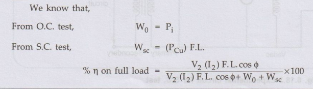
Thus
for any p.f. cos ϕ2 the efficiency can be predetermined. Similarly
at any load which is fraction of full load then also efficiency can be
predetermined as,
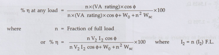
4. Calculation of Regulation
•
From S.C. test we get the equivalent circuit parameters referred to primary or
secondary.
•
The rated voltages V1, V2 and rated currents (I1)
F.L. and (I2) F.L. are known for the given transformer. Hence the
regulation can be determined as,
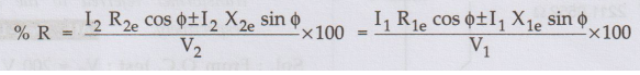
where
I1, I2 are rated currents for full load regulation.
For
any other load the currents I1, I2 must be changed by
fraction n.
I1,
12 at any other load = n (I1) F.L., n (I2)
F.L.
•
Thus regulation at any load and any power factor can be predetermined, without
actually loading the transformer.
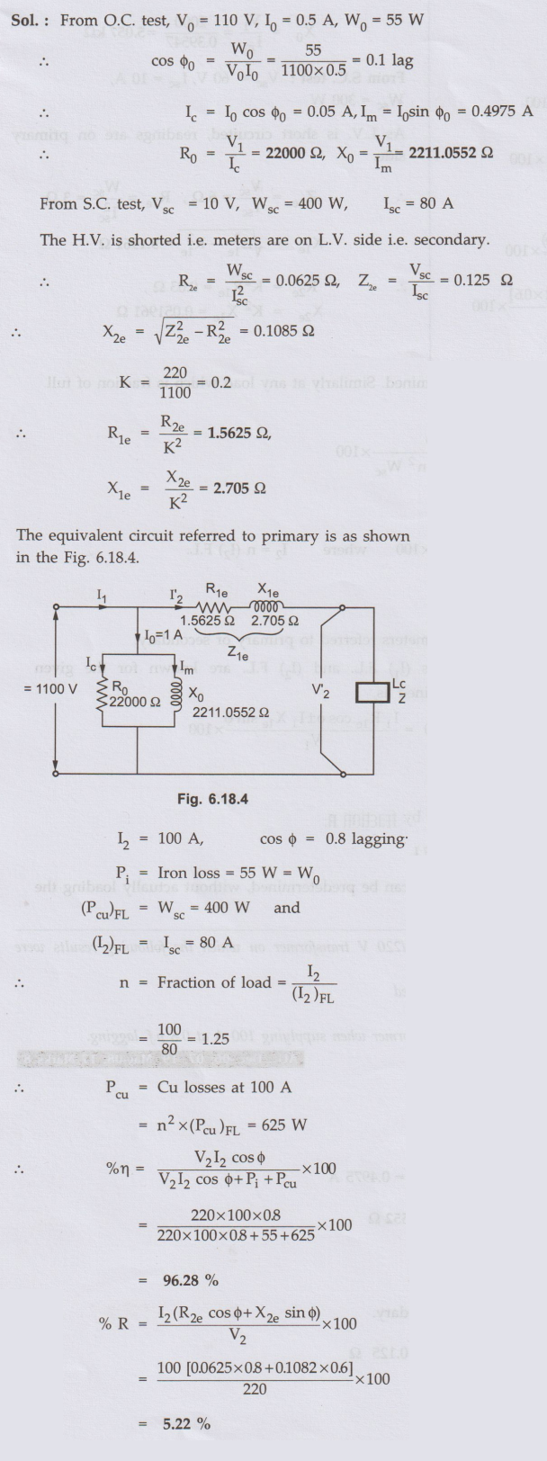
Ex. 6.18.1
Draw the equivalent circuit for a single
phase 1100/220 V transformer on which the following results were obtained:
i) 1100 V, 0.5 A, 55 W on primary,
secondary being open circuited
ii) 10 V, 80 A, 400 W on L.V. side,
H.V. being short circuited.
Calculate the voltage regulation
and efficiency for the above transformer when supplying 100 A at 0.8 p.f.
lagging. AU:
Dec.-06, 07, 19, May-08, 17 Marks 8
Sol. :
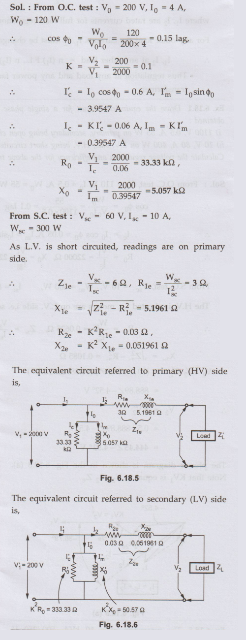
Ex. 6.18.2 The following data were obtained on
20 kVA, 50 Hz, 2000/200 V distribution transformer:
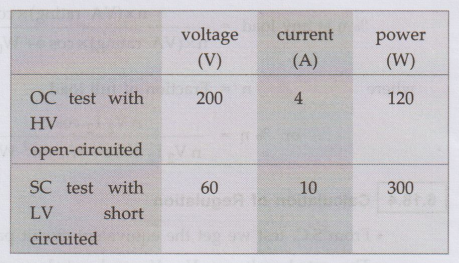
Draw the approximate equivalent
circuit of the transformer referred to the HV and LV sides respectively. AU: Dec.-16, May-11, Marks 16
Sol.:
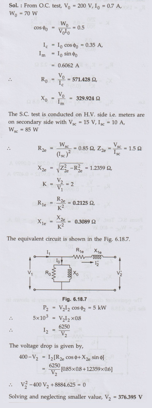
Ex. 6.18.3 Obtain the equivalent circuit of a
200/400 V, 50 Hz, 1-phase transformer from the following test data :
O.C. test: 200 V, 0.7 A, 70 W on
L.V. side
S.C. test: 15 V, 10 A, 85 W - on
H.V. side
Calculate the secondary voltage
when delivering 5 kW at 0.8 p.f. lagging, the primary voltage being 200 V. AU May-13, Marks 16
Sol. :
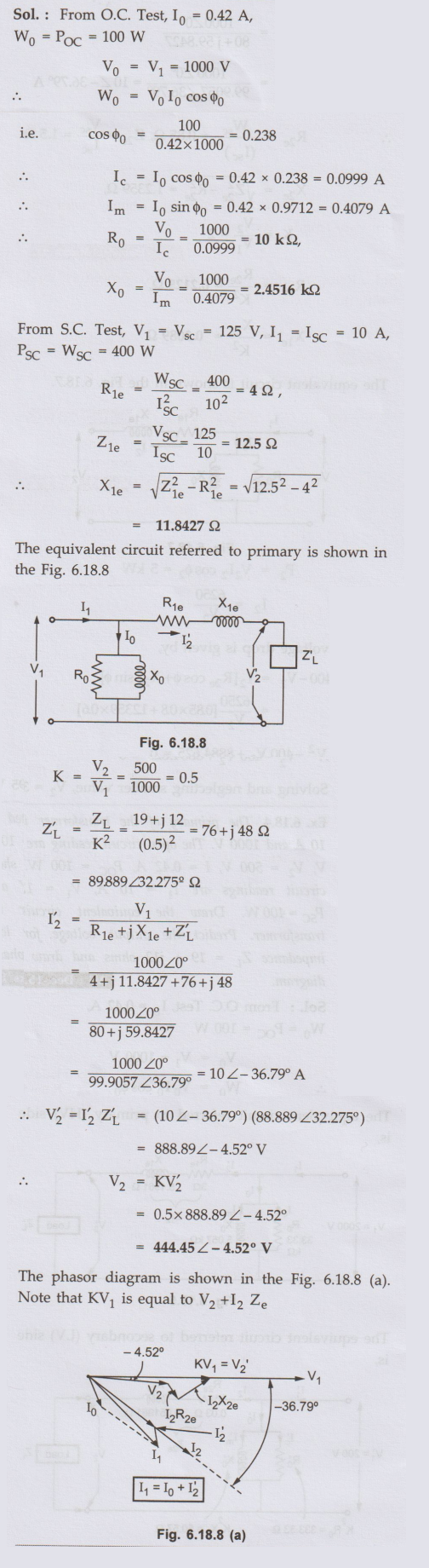
Ex. 6.18.4 The primary of the transformer is
rated at 10 A and 1000 V. The open circuit reading are V1 = 1000V, V2
= 500 V, I = 0.42 A, Poc =100Wcircuit readings are 11 Psc=400 W.The
short circuit ewadings are I1 = 10A, V1 = 125V and Psc
=400 W Draw the equivalent circuit for the transformer. Predict the output
voltage for the load impedance ZL =
19+ j12 ohms and draw the phasor diagram. AU
Dec.-15, Marks 16
Sol. :
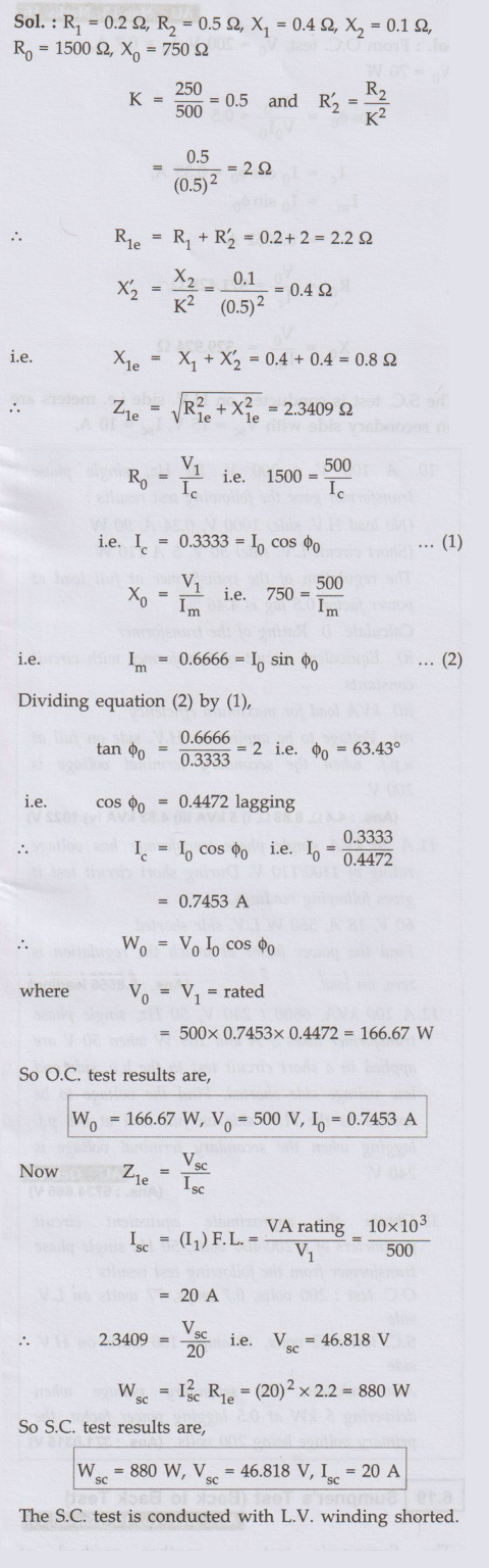
Ex. 6.18.5
The parameters of a 10 kVA, 500/250 V, 50
Hz, single phase transformer are as follows:
Primary resistance = 0.2 Ω, primary
reactance = 0.4 Ω Secondary resistance = 0.5Ω , secondary reactance = 0.1 Ω
Exciting circuit resistance and reactance = 1500 Ω, 750 Ω, respectively. Find
out the results of open circuit test and short circuit test.
Sol. :
Ex. 6.18.6 A 100 kVA, 6600 V/330 V, 50 Hz
single phase transformer took 10 A and 436 W at 100 V in a short circuit test,
the figures referring to high voltage side. Calculate the voltage to be applied
to the high voltage side on full load at power factor 0.8 lagging when the
secondary terminal voltage is 330 V. AU:
Dec.-10, Marks 12
Sol. :
Refer example 6.18.3 for the proceduce and verify the answer: V1 =
6734.666 V.
Review Questions
1. What are the tests
required to draw the equivalent circuit of a single phase transformer? How are
they conducted? AU: Oct.-02, May-10, 16, Marks 16
2. Explain how the
efficiency of a single phase transformer is estimated from the open circuit and
short circuit test. AU Dec.-06, Marks 8
3. With neat circuit
diagrams, explain the open-circuit and short-circuit tests conducted on single-phase
transformer. How to obtain regulation and efficiency from these tests ? AU: Dec.-08, May-12,
Marks 16
4. A 5 kVA, 500/250
V, 50 Hz, single phase transformer gave the following readings,
O.C. Test: 500 V, 1
A, 50 W (L.V. side open)
S.C. Test: 25 V, 10
A, 60 W (L.V. side shorted)
Determine:
i) The efficiency on
full load, 0.8 lagging p.f.
ii) The voltage
regulaion on full load, 0.8 leading p.f.
iii) The efficiency
on 60 % of full load, 0.8 leading p.f.
iv) Draw the
equivalent circuit referred to primary and insert all the values in it.
(Ans. % η = 97.32 %,
% R = -1.95 %, % n = 97.103 %)
5. The open circuit
and short circuit tests on a 10 kVA, 125 / 250 V, 50 Hz, single phase
transformer gave the following results :
O.C. test: 125 V, 0.6
A, 50 W (on L.V. side)
S.C. test: 15 V, 30
A, 100 W (on H.V. side)
Calculate: i) Copper loss on full load, ii) Full load
efficiency at 0.8 leading p.f.
iii) Half load
efficiency at 0.8 leading p.f.,
iv) Regulation at
full load, 0.9 leading p.f.
(Ans.: % η on full
load = 97.23%, % non half load = 97.69 %, % R = 1.8015 %)
6. The open circuit
and short circuit tests on a kVA, 250 / 125 V, 50 Hz, single phase transformer
gave the following results :
O.C. Test: 250 V, 0.7
A 90 W (H.V. side) and
S.C. Test: 12 V, 30
A, 90 W (L.V. side)
Calculate: i) The
full load efficiency ii) The voltage on L.V. side when supplying full load
current both at 0.8 leading power factor.
(Ans.: % η= 94.11 %,
Terminal V2 = 131.0952 V)
7. From the following
test data, calculate % efficiency and % regulation at half-load and 0.8
Slagging p.f. for 1.5 kVA, 220 V/110 V, single phase, 50 Hz transformer.
O.C. test: 220 V, 0.7
A, 32 W and S.C. test: 9 V, 6.82 A, 44 W
(measuring
instruments connected on H.V. side in both the tests)
(Ans. % R = 2.028 %,
% η = 93.3125 %)
8. A 40 kVA, 400/200
V, 50 Hz, single phase o transformer gave the following results.
Open circuit test:
400 V, 5 A, 500 W and Short circuit test: 10 V, 50 A, 150 W
i) Draw the
equivalent circuit of the transformer and show the values of resistance and
reactance interms of primary side.
ii) Calculate the
terminal voltage, when the transformer delivers the solid output at a p.f. of
0.8 lagging on the L.V. side.
(Ans. : i) R1e
= 0.06Ω, Z1e = 0.2Ω, X1e = 0.1907 Ω ii) 191.88 V)
9. A 1-phase; 50 kVA,
2400/120 V, 50 Hz transformer gave the following results.
O.C. test with
instruments on the L.V. side 120 V, 9.65 A, 396 W
S.C. test with
instruments on the H.V. side 92 V, 0 20.8 A, 810 W
Calculate:
i) The equivalent
circuit constants and draw the equivalent circuit.
ii) The efficiency
when rated kVA is delivered to a load having a power factor of 0.8 lagging.
iii) The voltage
regulation.
(Ans. i) 1.8662 Ω
4.416 Ω, 4.00222, 97.07 %, 3.38%)
10. A 100 V / 200 V,
50 Hz, single phase transformer gave the following test results
(No load H.V. side)
1000 V, 0.24 A, 90 W
(Short circuit L.V. side) 50 V, 5 A 110 W
The regulation of the
transformer at full load at power factor 0.8 lag is 4.46 %.
Calculate i) Rating
of the transformer
ii) Equivalent
circuit of transformer with circuit constants
iii) kVA load for
maximum efficiency
iv) Voltage to be
applied on H.V. side on full at u.p.f. when the secondary terminal voltage is
200 V.
(Ans.: 4.4'Ω, 8.89 Ω,
i) 5 kVA iii) 4.52 kVA iv) 1022 V)
11.A 20 kVA single
phase transformer has voltage rating of 1100/110 V. During short circuit test
it gives following readings,
60 V, 18 A, 560 W
L.V. side shorted
Find the power factor at which the regulation is zero, on load.
(Ans. : 0.8556 leading)
12.A 100 kVA, 6600 / 240 V, 50 Hz, single phase transformer takes 5 A and 109 W when 50 V are applied in a short circuit test to the h.v. side and low voltage side shorted. Find the voltage to be applied to the H.V. side on full load at 0.8 p.f. lagging when the secondary terminal voltage is 240 V.AU: Oct.-02
(Ans.: 6734.666 V)
13. Obtain the
approximate equivalent circuit parameters of a 200/400 volts, 50 Hz single
phase transformer from the following test results:
O.C. test: 200 volts, 0.7 amps, 77 watts on
L.V. side
S.C. test: 12 volts,
10 amps, 100 watts on H.V. side
Also calculate the secondary voltage when delivering 5 kW at 0.5 lagging power factor, the primary voltage being 200 volts.
(Ans. : 371.0315 V)
Electrical Machines: Unit IV: Single Phase Transformer : Tag: : Single Phase Transformer - Open Circuit and Short Circuit Tests
Related Topics
Related Subjects

Electrical Machines I
EE3303 EM 1 3rd Semester EEE Dept | 2021 Regulation | 3rd Semester EEE Dept 2021 Regulation