Microprocessors and Microcontrollers: Unit IV: (e) Keyboard and Display Controller - 8279
Operating Modes
Input and Display
Review Questions 1. What do you mean by encoded scan and decoded scan ? 2. Explain the input modes provided by 8279. 3. Explain the terms 2-key lockout and N-key rollover. 4. Why maximum size of keyboard matrix is 8 × 8 = 64, when interfaced with 8279 ? 5. Explain the display modes provided by 8279. 6. Explain the working of 8279 as a keyboard/display controller and explain its command registers
Operating Modes
1. Input Modes
The
8279 provides 3 basic input modes :
•
Scanned keyboard
•
Scanned sensor matrix
•
Strobed input
1.
Scanned keyboard
In
this mode, keyboard can be scanned in two ways : Encoded scan and Decoded scan.
Encoded
scan : In the encoded scan, scan lines (SL2 -
SL0) are decoded externally to provide 8 scan lines. We know that
8279 provides 8 returns lines. Therefore, the maximum size of keyboard matrix
is 8 × 8 = 64. When the key is pressed, 8279 stores the encoded status of scan
lines and return lines along with the status of SHIFT and CNTL/STB keys into
the FIFO RAM, as shown in the Fig. 12.6.1.
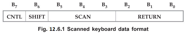
CNTL
is the MSB of the character and SHIFT is the next most significant bit. The
next three bits are from the scan counter. The last three bits indicate to
which return line the key is connected. With this 8-bit key code 8279 can
recognize 256 (28) different characters.
Example
12.6.1 Find the key code for condition given below :
CNTL/STB SHIFT keys are open.
The
pressed key is connected to scan line 2 and return line 4.
Solution
:
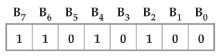
CNTL
= 1
SHIFT
= 1
Scan
Code = 0 1 0 (scan line 2)
Return
code = 1 0 0 (return line 4)
ஃ Key code = D4H
Decoded
scan : In the decoded mode, the internal decoder decodes
the least significant 2 bits of scan lines internally to provide four possible
combinations on the scan lines (SC3 – SC0) : 1110, 1101,
1011 and 0111. Therefore maximum size of keyboard matrix is 8 × 4 = 32. In this
mode, keycode is generated in similar way as in the encoded mode, only bit 5 of
keycode is always 0. Therefore, 8279 can recognize only 128 (27)
characters.
The
scanned keyboard mode allows key depressions in 2-key lockout or N-key rollover
mode with key debounce.
2-key
lockout : In this mode, simultaneous key depression is not
allowed. When any key is depressed, the debounce logic is set and 8279 checks
for any other key depress during next two scans. Now we will see how this mode
reacts with three possible conditions that can occur during debounce scanning.
Condition
1 :
If other key depress not found during next two scans, it is a single key
depression and the key code is entered into FIFO RAM along with the status of
CNTL and SHIFT lines. If the FIFO was empty, IRQ will be set to signal the CPU
that there is an entry in the FIFO RAM. If the FIFO RAM was full, the key will
not be entered and the error flag will be set.
Condition
2 :
If another key depress is encountered, no entry to the FIFO can occur. If all
other keys are released before first one, then it will be entered to the FIFO.
If first key is released before any other, it will be entirely ignored.
Condition
3 : If
two keys are depressed within the debounce cycle, it is a simultaneous
depression. Neither key will be recognized until one key remains depressed
alone. The last key will be treated as a single key depression.
N-Key
Rollover : In N-Key rollover, each key depression is treated
independently from all others. When a key is depressed, the debounce logic is
set and 8279 checks for key depress during next two scans. Now we will see how
this mode reacts with three possible conditions that can occur during debounce
scanning.
Condition
1 : If
key is still pressed then key is entered into the FIFO.
Condition
2 :
If other keys are pressed, they are recognized and entered into the FIFO.
Condition
3 : If
a simultaneous depression occurs, the keys are recognized and entered according
to the keyboard scan found them.
2.
Scanned sensor matrix : In the sensor matrix mode, image
of the sensor matrix is kept in the sensor RAM. The status of the sensor
switches are input directly to the sensor RAM. 8279 scans rows one by one and
stores the status of each row in the corresponding location in the sensor RAM.
For example, when 8279 scans first row of sensor matrix it stores the status of
first row in the location 0 of the sensor RAM. At the end of sensor matrix scan
if any sensor value change is detected then 8279 sets 'S' bit in the status
register and activates the IRQ signal. In the autoincrement mode, the IRQ line
is cleared by issuing End of Interrupt command, otherwise it is cleared by the
first data read operation. When multiple changes in the sensor matrix occurs, multiple
interrupts are generated. In sensor matrix mode, the debounce logic is
inhibited. Although it is inhibited, sensor matrix mode has the advantage that
CPU knows how long the sensor was closed and when it was released. The scanned
keyboard mode can only indicate validated key closure. In encoded mode, size of
sensor matrix is 8 × 8 whereas in decoded mode size of sensor matrix is 8 × 4.
In both the modes CNTL and SHIFT lines are ignored.
3.
Strobed input mode
In
the strobed input mode, data is entered to the FIFO RAM from the returned
lines. The data is entered at the rising edge of the CNTL/STB signal.
2. Display Modes
The
8279 provides 2 basic output modes
•
Left Entry (type writer type)
•
Right Entry (calculator type)
a.
• Left Entry (type writer type)
In
the left entry mode, 8279 displays characters from left to right in the
multiplexed displays like a typewriter. In this, each display position directly
corresponds to a byte (or nibble) in the display RAM. Address 0 in the RAM is
the left-most display character and address 15 (or address 7 in 8 character
display) is the right most display.
The
characters can be displayed on the specific digit by loading character code in
the corresponding location in the display RAM.
Autoincrement
in Left Entry
In
left entry mode, if autoincrement flag is set to 1 after each write operation
display RAM address is incremented by one so that it will point the next
location in the display RAM. This autoincrement facility allows user to load
display RAM in a sequential manner, and it is not necessary to specify display
RAM address for each write operation.
b.
Right Entry
In
the right entry mode, 8279 displays characters from right to left in the
multiplexed display like a calculator. The first entry is displayed on the right
most display. The next entry is also displayed on the right most display after
the display is shifted left one character.
When
new character is entered, it shifts all previous characters left by one
position and displays new entry on the right most display.
Autoincrement
in Right Entry
In
the right entry mode, autoincrementing and non autoincrementing have the same
effect as in the left entry except if the address sequence is changed.
Review Questions
1. What do you mean by
encoded scan and decoded scan ?
2. Explain the input
modes provided by 8279.
3. Explain the terms
2-key lockout and N-key rollover.
4. Why maximum size of keyboard matrix is 8 × 8 = 64,
when interfaced with 8279 ?
5. Explain the display
modes provided by 8279.
6. Explain the working
of 8279 as a keyboard/display controller and explain its command registers
AU : Dec -16, Marks 16
Microprocessors and Microcontrollers: Unit IV: (e) Keyboard and Display Controller - 8279 : Tag: : Input and Display - Operating Modes