Digital Logic Circuits: Unit II: Combinational Circuits
Parallel Adder/Subtractor
Combinational Circuits
• The addition and subtraction operations can be combined into one circuit with one common binary adder. This is done by including an exclusive-OR gate with each full adder.
Parallel Adder/Subtractor
•
The addition and subtraction operations can be combined into one circuit with
one common binary adder. This is done by including an exclusive-OR gate with
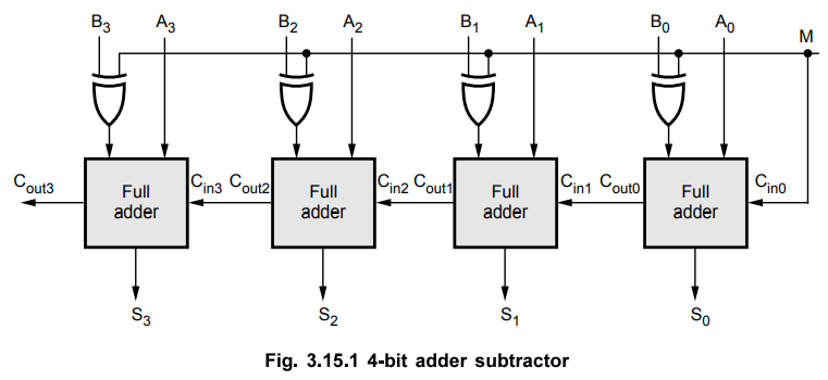
each full adder, as shown in Fig. 3.15.1. The mode input M controls the
operation of the circuit. When M = 0, the circuit is an adder, and when M = 1,
the circuit becomes a subtractor. Each exclusive - OR gate receives input M and
one of the inputs of B. When M = 0, we have B ⊕ 0 = B. The full-adders receive the
value of B, the input carry is 0 and the circuit performs A plus B. When M = 1,
we have B ⊕
1 = 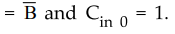 . The B inputs are all complemented and a 1 is added through the
input carry. The circuit performs the operation A plus the 2's complement of B,
i.e. A - B.
. The B inputs are all complemented and a 1 is added through the
input carry. The circuit performs the operation A plus the 2's complement of B,
i.e. A - B.
•
The parallel adder is ripple carry adder in which the carry output of each
full-adder stage is connected to the carry input of the next higher-order
stage. Therefore, the stun and carry outputs of any stage cannot be produced
until the input carry occurs; this leads to a time delay in the addition
process. This delay is known as carry propagation delay.
•
One method of speeding up this process by eliminating inter stage carry delay
is called look ahead-carry addition. This method utilizes logic gates to look
at the lower-order bits of the augend and addend to see if a higher-order carry
is to be generated.
Review Question
1. What is the drawback in binary parallel adder ? How can it be rectified ?
Digital Logic Circuits: Unit II: Combinational Circuits : Tag: : Combinational Circuits - Parallel Adder/Subtractor
Related Topics
Related Subjects

Digital Logic Circuits
EE3302 3rd Semester EEE Dept | 2021 Regulation | 3rd Semester EEE Dept 2021 Regulation