Electromagnetic Theory: Unit II: (b) Conductors, Dielectrics and Capacitance
Parallel Plate Capacitor
Formula, Example Solved Problems
The lower plate, plate 1 carries the positive charge and is distributed over it with a charge density + ρs. The upper plate, plate 2 carries the negative charge and is distributed over its surface with a charge density - ρs.
Parallel Plate Capacitor
AU
: May-95, 04, 06, 10, 14, 17
•
A parallel plate capacitor is shown in the Fig. 5.13.1. It consists of two
parallel metallic plates separated by distance 'd'. The space between the
plates is filled with a dielectric of permittivity Ɛ. The lower plate, plate 1
carries the positive charge and is distributed over it with a charge density + ρs.
The upper plate, plate 2 carries the negative charge and is distributed over
its surface with a charge density - ρs. The plate 1 is placed in z = 0 i.e. xy
plane hence normal to it is z direction. While upper plate 2 is in z = d plane,
parallel to xy plane.
•
Let A = Area of cross section of the plates in m2

•
This is magnitude of charge on any one plate as charge carried by both is equal
in magnitude. To find potential difference, let us obtain ![]() between the
plates.
between the
plates.
•
Assuming plate 1 to be infinite sheet of charge,
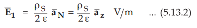
•
The ![]() is normal at the boundary between conductor and dielectric without
any tangential component.
is normal at the boundary between conductor and dielectric without
any tangential component.
•
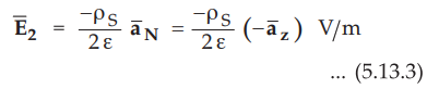
While for plate 2, we can write
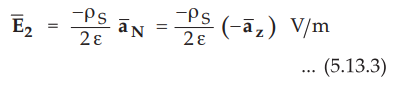
•
The direction of ![]() is downwards i.e. in -
is downwards i.e. in - ![]() direction.
direction.
In
between the plates,
The
potential difference is given by,
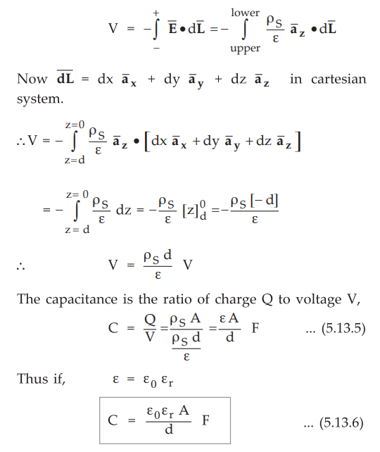
It
can be seen that the value of capacitance depends on,
1.
The permittivity of the dielectric used.
2.
The area of cross section of the plates.
3.
The distance of separation of the plates.
It
is not dependent on the charge or the potential difference between the plates.
Ex.
5.13.1 Determine the value of capacitance between 2 square plates cross
sectional area 1 sq. cm separated by 1 cm placed in a liquid whose die-electric
constant is 6 and the relative permittivity of free space is 8.854 pF/m.
AU
; May-04, Marks 4
Sol.
:

Ex.
5.13.2 A parallel plate capacitor has an area of 08 m2, separation of 0.1 mm
with a dielectric for which £r = 1000 and a field of 106 V/m.
Calculate
C and V.
Solution
:

Ex,
5.13,3 The relative permittivity of dielectric in a parallel plate capacitor
varies linearly from 4 to 8. If distance of separation of plates is 1 cm and
area of cross section of plates is 12 cm2, find the capacitance.
Sol.
:
The arrangement is shown in the Fig. 5.13.2.

The
Ɛr varies linearily from 4 to 8, along x direction. The equation for linear
behaviour is,

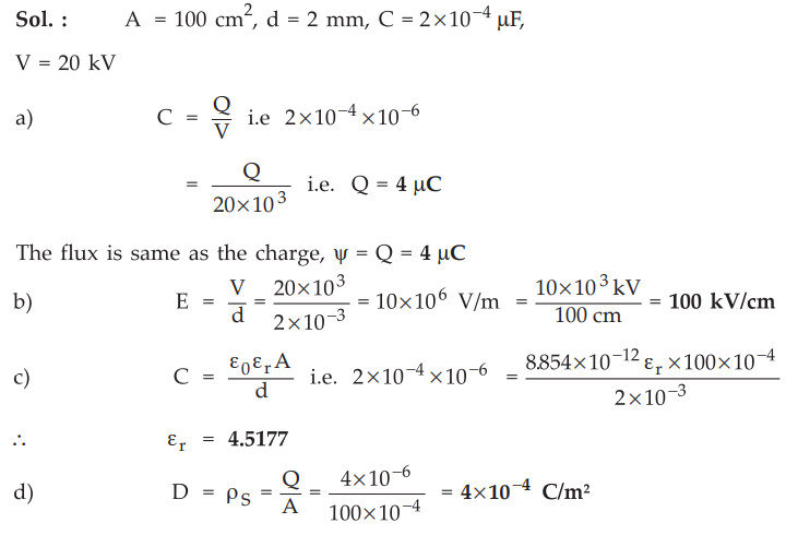
Ex.
5.13.4 The capacitance of the condenser formed by the two parallel metal
sheets, each 100 cm in area separated by a dielectric 2 mm thich is 2 × 10⁻⁴
µF. A potential of 20 kV is applied to it. Find :
a)
Electric flux b) Potential gradient in kV/m c) The relative permittivity of the
material and d) Electric flux density.
AU
: May-95, 06, Marks 8
Sol.
:
Ex.
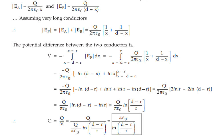
5.13.5 Find the capacitance between two parallel conductors, mtrs. Both wire
are carrying the current in opposite direction.
Sol. : The arrangement of the conductors is shown in the Fig. 5.13.3.

The conductors are
carrying currents in opposite directions. Consider point P at a distance x from
the conductor A. The fields acting at point P due to both the conductors are in
same directions. The magnitudes of the fields at point P due to both the
conductors are,
Examples
for Practice
Ex.
5.13.6 The capacitance of the condenser formed
by the two parallel metal sheets, each 100 cm2 in area separated by a dielectric
2 mm thich is 2 × 10⁻⁴ µF. LIF. A potential of 20 kV is applied to
it. Find :
a)
Electric flux b) Potential gradient in kV/m c) The relative permittivity of the
material and d) Electric flux density.
[Ans.:
4 iiC, 100 kV/cm, 4.5177, 4 x 10 4 C/m2]
Ex,
5.13.7 The electric field intensify in
polystyrene (Ɛr = 2.55) filling the space between the plates of a
parallel plate capacitor is 10 kV/m. The distance between the plates is 1.5 mm.
Calculate : i) The surface charge density of free charge on the plates ii) The
potential difference between the plates.
[Ans.:
2.2577 × 10⁻⁷ C/m2,15 V]
Ex.
5.13.8 Find the capacitance of a parallel plate
capacitor if A = 1 m2, distance between the plates is 1 mm, voltage gradient is
10s V/m and charge density on the plate is 2 µC / m2.
[Ans.:
20 nF]
Review Question
1. Derive the expression for a capacitance of a parallel plate
capacitor.
Electromagnetic Theory: Unit II: (b) Conductors, Dielectrics and Capacitance : Tag: : Formula, Example Solved Problems - Parallel Plate Capacitor
Electromagnetic Theory: Unit II: (b) Conductors, Dielectrics and Capacitance
Under Subject

Electromagnetic Theory
EE3301 3rd Semester EEE Dept | 2021 Regulation | 3rd Semester EEE Dept 2021 Regulation
Related Subjects
Probability and complex function
MA3303 3rd Semester EEE Dept | 2021 Regulation | 3rd Semester EEE Dept 2021 Regulation
Electromagnetic Theory
EE3301 3rd Semester EEE Dept | 2021 Regulation | 3rd Semester EEE Dept 2021 Regulation

Digital Logic Circuits
EE3302 3rd Semester EEE Dept | 2021 Regulation | 3rd Semester EEE Dept 2021 Regulation

Electron Devices and Circuits
EC3301 3rd Semester EEE Dept | 2021 Regulation | 3rd Semester EEE Dept 2021 Regulation

Electrical Machines I
EE3303 EM 1 3rd Semester EEE Dept | 2021 Regulation | 3rd Semester EEE Dept 2021 Regulation

C Programming and Data Structures
CS3353 3rd Semester EEE, ECE Dept | 2021 Regulation | 3rd Semester EEE Dept 2021 Regulation