Transmission and Distribution: Unit II: (b) Corona
Parameters Related to Corona
Critical Disruptive Voltage - Critical Visual Disruptive Voltage - Corona Power Loss
The various parameters related to corona effect are, i) Critical disruptive voltage, ii) Critical visual disruptive voltage and iii) Corona power loss
Parameters Related to
Corona
AU : May-06, 07, 13, 14, 15, Dcc.-03,
05, 12, 16
The various parameters related to corona
effect are, i) Critical disruptive voltage, ii) Critical visual disruptive voltage
and iii) Corona power loss
1. Critical Disruptive Voltage
The critical disruptive voltage is
defined as the minimum phase to neutral voltage at which corona occurs. It is
denoted as Vd.
For a given transmission conductor, the
gradient is maximum at the surface i.e. at a distance of radius r from the
centre. So if there are two conductors each of radius r and distance between
them is d then the potential gradient at the surface of the conductor is given
by,
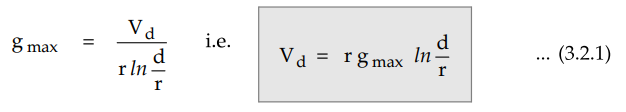
At the critical disruptive voltage, the
complete disruption of dielectric occurs. At this voltage, the potential
gradient developed is equal to breakdown strength of the air which is denoted
as go. At a normal temperature of 251 and pressure of 76 cm of Hg the value of
go is 30 kV/cm.
Hence Vd can be expressed as,
Vd = rgo ln d / r ...
(3.2.2)
But for any other temperature and
pressure the value of go is different. It is given by,
g'o = δ go where δ = Air density
correction factor ... (3.2.3)
The air density correction factor which
depends on the pressure and temperature is given by,
δ = 3.92 b / 273 + t ... (3.2.4)
where
b = Barometric pressure in cm of Hg and
t = Temperature in ° C
Hence Vd can be further
expressed as,
Vd = rδgo ln = d / r ... (3.2.5)
The equation (3.2.5) is valid if the
conductors are solid and having uniform smooth surface. But the surface
conditions are different for large cables and stranded conductors. Hence another
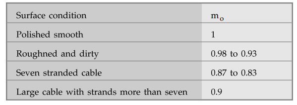
correction factor must be introduced in Vd. Such a factor is called
irregularity factor denoted as mo. This factor is the average value of the
ratio of breakdown voltage for irregular conductor to the smooth conductor.
The table gives the values of mo
for various cases.
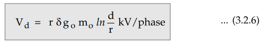
Hence the final expression for the
critical disruptive voltage becomes,
2. Critical Visual Disruptive Voltage
When the voltage applied is equal to
critical disruptive voltage, the corona starts but it cannot be visible. To
have it visible, the charged ions in air require further ionization and hence
surface gradient must increase and reach a value gv. The voltage required
to cause a gradient of gv at the surface is called critical visual
disruptive voltage denoted as Vv.
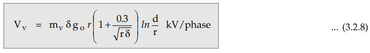
The critical visual disruptive voltage
is the minimum phase to neutral voltage at which corona glow appears and
visible all along the conductors.
The distance between gv and go is called
the energy distance which is equal to (r + 0.301 √r) for two parallel
conductors and (r + 0.308 √r) for co-axial conductors. Thus g T is not constant
and depends on the size of the conductors. It is given by,
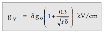 ... (3.2.7)
This is for parallel conductors.
The irregularity factor is slightly
different denoted as mv. Its value is 1.0 for polished conductors, 0.98 to 0.93
for rough conductors and 0.72 for the local corona on stranded conductors. For
the general corona its value is 0.82. The conductor surface is not regular and
hence corona does not start simultaneously all along the surface. It starts at
the portions which are pointed. This is called local corona.
Considering all these factors the
critical visual disruptive voltage can be expressed as,
If Vd and Vv r.m.s.
values are to be calculated then r.m.s. value of go must be used.

3. Corona Power Loss
The ions produced in the air due to
corona are moving. The energy required to keep them moving is derived from the
supply system. This additional power required which is dissipated in the form
of heat, sound and light in case of corona, is called corona loss.
The expression for the corona loss is
given by Peek as,
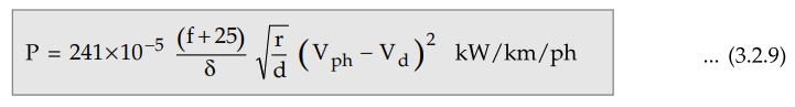
where
f = Supply frequency in Hz
Vph = Phase to neutral r.m.s.
voltage in kV
Vd = Critical disruptive
voltage (r.m.s.) per phase
The above formula is called Peek's
formula and applicable for fair conditions.
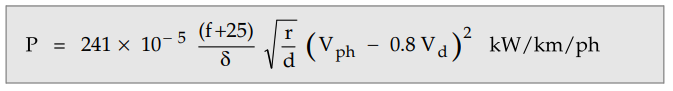
Key Point
If the weather is rainy and stormy then critical disruptive voltage Vd gets
reduced by the factor 0.8.
Hence corona power loss in rainy
conditions is given by,
The formula is useful when corona losses
are predominant and the ratio of (Vph/Vd) is above 1.8.
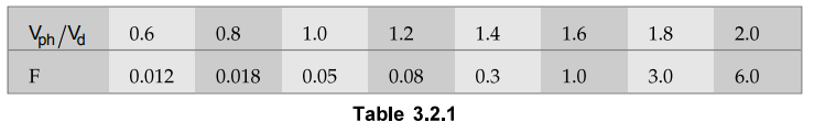
If the ratio of (Vph/Vd)
is less than 1.8, Peterson's formula must be used, which is given by,
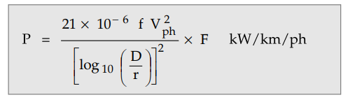
where F is the factor which varies as
the ratio Vph/Vd given by,
The corona loss in 3 phase extra high
voltage lines, having voltage level more than 400 kV, in rainy condition is
given by,
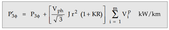
where
P3ϕ - Total three phase loss in rainy condition for EHV line
P3ϕ - Total three phase loss
in fair condition for EHV line
J - Constant = 4.37 × 10⁻¹⁰
at 400 kV
K - Wetting coefficient = 10
i - Subconductor
m - Total number of subconductors
Vi - Voltage gradient on
outer conductor in kV/cm
p - An exponential index generally 5
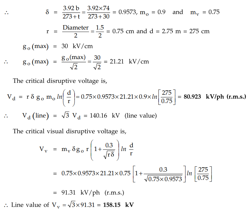
Example 3.2.1
Determine the critical disruptive voltage and the critical visual disruptive
voltage for a 3 phase, 50 Hz, 132 kV line situated in a temperature of 30°C and
at a barometric pressure of 74 cm. The conductor diameter is 1.5 cm while the
equilateral spacing between the conductors is 2.75 m. The surface irregularity
factor is 0.9 while mv = 0.75.
Solution :
Given b = 74 cm and t = 30 ° C
Example 3.2.2
A particular 3 phase transmission line has total corona loss of 57 kW at 110
kV and corona loss of 99 kW at 114.8 kV. Calculate the critical disruptive
voltage per phase and corona loss at 120 kV.
Solution :
The total corona loss is given by,
P = 3 × Corona loss per phase
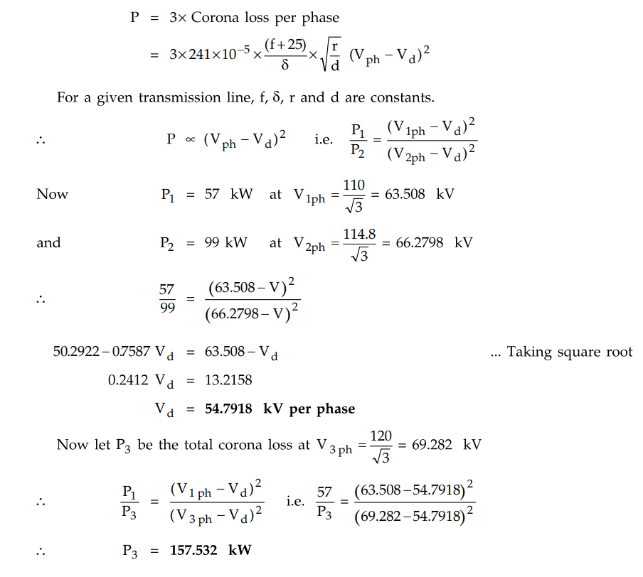
This is the total corona loss at 120 kV
of system line voltage.
Example 3.2.3
A 3 phase overhead line operates at 132 kV, 50 Hz. The conductors are spaced
at the corners of an equilateral triangle with a spacing of 3 m between
centres. Determine the conductor diameter required to prevent corona under fair
weather conditions. The air temperature is 22°C and barometer pressure is 72.5
cm, Vd = 150 kV.
Solution:
b = 72.5 cm, t = 22°C, d = 3 m = 300 cm
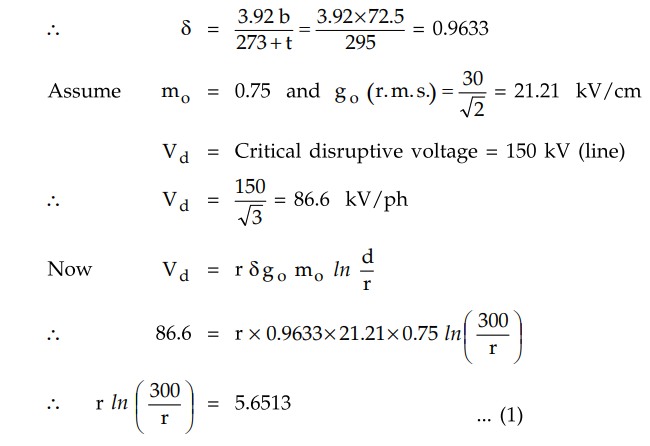
The equation cannot be solved
mathematically. Use trial and error method.
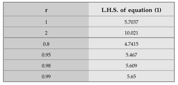
Hence the radius of the conductor is
0.99 cm.
So conductor diameter to prevent corona
must be 1.98 cm, under fair weather conditions.
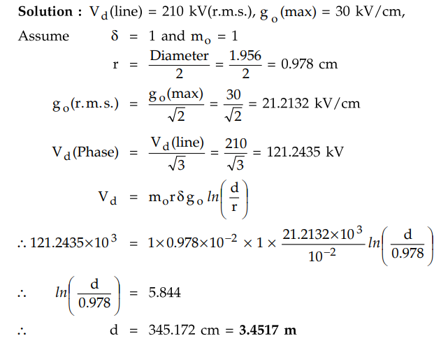
Example 3.2.4
A 132 kV, 3 phase line with 1.956 cm diameter conductors in built so that
corona takes place, if the line voltage exceeds 210 kV (r.m.s.). If the value
of potential gradient at which ionization occurs can be taken as 30 kV per cm,
find the spacing between the conductors.
Solution :
Example 3.2.5
A conductor with 2.5 cm dia is passed centrally through a porcelain bushing
having er = 4 and internal and external diameters of 3 cm and 9 cm,
respectively. The voltage between the conductor and an earthed clamp
surrounding the porcelain is 20 kV r.m.s. Determine whether corona will be
present in the air-space round the conductor. Solution : Let g 1max = Maximum
gradient on the surface of conductor.
Solution :
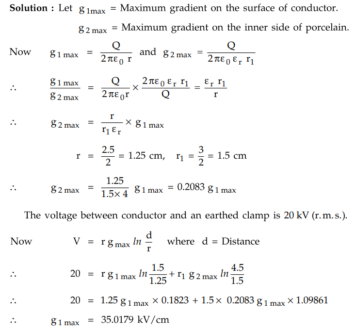
This exceeds the gradient of air 21.1
kV/cm hence corona will be present in the air space round the conductor.
Example 3.2.6
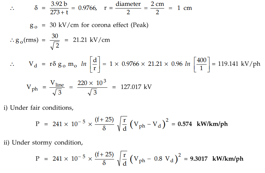
A three phase, 50 Hz, 220 kV transmission line consists of conductor of 2.0
cm diameter and spaced equilaterally at a distance of 4 m. The line conductors
have smooth surface with value of surface irregularity factor 0.96. The
barometric pressure is 73 cm of Hg and temperature of 20 °C. Determine the fair
and stormy weather corona loss per km per phase.
Solution :
b = 73 cm, t = 20 °C, d = 4 m = 400 cm, mo = 0.96, f = 50 Hz
Example 3.2.7
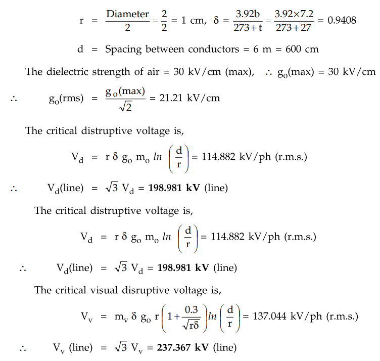
A 3-phase transmission line is having three conductors equilaterally spaced 6
m apart. The diameter of each conductor is 2 cm. The air temperature is 27 °C
and pressure is 72 cm of Hg. If the surface factor is 0.82 and irregularity
factor is 0.9, find the critical disruptive and visual disruptive voltages.
AU: May-07, Marks 8
Solution:
Given: b = 72 cm, t = 27 °C, m = 0.9 m mv = 0.82
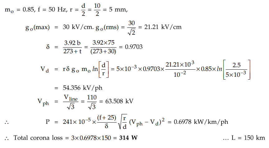
Example 3.2.8 Estimate
the corona loss for a three-phase, 110 kV, 50 Hz, 150 km long transmission line
consisting of three conductors each of 10 mm diameter and spaced 2.5 m apart in
a equilateral triangle formation. The temperature of air is 30° C and the
atmospheric pressure is 750 mm of mercury. Assume the irregularity factor as
0.85. Ionization of air may be assumed to take place at a maximum voltage
gradient of 30 kV/cm.
Solution :
b = 750 mm = 75 cm, t = 30° C, d = 2.5 m = 250 cm,
Review Questions
1. Explain disruptive critical voltage.
2. Explain visual critical voltage.
3. Write a short note on corona power loss.
4. Write a Peek’s formula used for calculating corona loss under
fair weather conditions and under storm conditions.
5. A 3-phase transmission line is having three conductors equilaterally
spaced 6 m apart. The diameter of each conductor is 2 cm. The air temperature
is 27 °C and pressure is 72 cm of Hg. If the surface factor is 0.82 and
irregularity factor is 0.9, find the critical disruptive and visual disruptive
voltages.
[Ans.: 198.981 kV (line), 237.367 kV (line)]
6. A three phase equilaterally spaced transmission line has a total
corona loss of 53 kW at 106 kV and a loss of 98 kW at 110.9 kV. What is the
disruptive critical voltage between lines ? What is corona loss at 113 kV ?
[Ans.: 92.3815 kV, 120.906 kW]
7. A3 phase line has conductors of 2 cm in diameter, spaced
equilaterally, 1 m apart. If the dielectric strength of air is 30 kV/cm (max),
find the critical disruptive voltage for the line. Air density factor 8 = 0.952
and irregularity factor mo = 0.9.
[Ans.: 144.95 kV (r.m.s.)]
8. A 3 phase, 50 Hz, 132 kV transmission line consists of
conductors of 1.17 cm diameter and spaced equilaterally at a distance of 3 m.
The conductors have smooth surface with mo = 0.96. The barometric pressure is
72 cm ofHg and the temperature is 20°C. Determine corona loss per km per phase
under fair and foul weather conditions.
[Ans.: 0.1767 kW/km/phase, 2.9716 kW/km/phase]
9. Find the corona characteristics of a 110 kV, 50 Hz, 3 phase
transmission line 175 km long consisting of three 1 cm diameter stranded
conductors arranged in the form of a delta with a spacing of 3 m. The
barometric pressure is 74 cm of mercury and temperature 26 ° C, surface factor
is 0.85. For local corona, surface factor is 0.72 and it is 0.82 for general
corona.
[Ans.: 55.64 kV(r.m.s.) per phase, 67.442 kV/ph (r.m.s.), 76.809 kV/ph (r.m.s.), 247.246 kW, 1441.095 kW, 20.16 kW]
Transmission and Distribution: Unit II: (b) Corona : Tag: : Critical Disruptive Voltage - Critical Visual Disruptive Voltage - Corona Power Loss - Parameters Related to Corona
Related Topics
Related Subjects

Transmission and Distribution
EE3401 TD 4th Semester EEE Dept | 2021 Regulation | 4th Semester EEE Dept 2021 Regulation