Microprocessors and Microcontrollers: Unit IV: (e) Keyboard and Display Controller - 8279
Pin Diagram
CPU Interface , Keyboard and Display Data
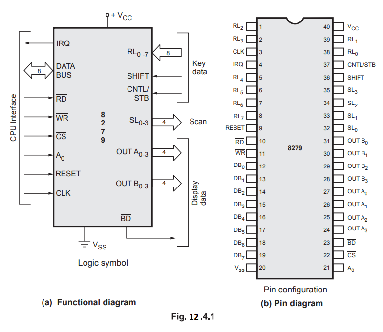
Fig. 12.4.1 shows functional and pin diagram of 8279. It is a 40 pin device and looking at Fig. 12.4.1 (a) we can see that these pins are divided in four functional groups :
Pin Diagram
Fig.
12.4.1 shows functional and pin diagram of 8279. It is a 40 pin device and
looking at Fig. 12.4.1 (a) we can see that these pins are divided in four
functional groups :
•
CPU interface
•
Key data
•
Display data
•
Scan
1. CPU Interface Pins
As
shown in Fig. 12.4.2 (a), it consists of 8-bit data bus,  RESET, CLK
and IRQ lines.
RESET, CLK
and IRQ lines.
DB0-DB7
: Bi-directional data bus : All data, commands and status
information between the CPU and the 8279 are transmitted on these
bi-directional 8-bit data bus.
![]() : Read : It is an active low signal. When
: Read : It is an active low signal. When ![]() signal
is low CPU reads the contents of selected register (display RAM, status
register or FIFO RAM) from 8279; depending on the type of command and the
status of the A0 signal.
signal
is low CPU reads the contents of selected register (display RAM, status
register or FIFO RAM) from 8279; depending on the type of command and the
status of the A0 signal.
![]() : Write : It is an active low signal. When
: Write : It is an active low signal. When ![]() signal
is low, CPU loads the data into selected register (control register or display
register) depending on the status of A0 signal.
signal
is low, CPU loads the data into selected register (control register or display
register) depending on the status of A0 signal.
A0
: Address line : When A0 is high, signals are
interpreted as a command or status. When A0 is low signals are
interpreted as a data.
![]() : Chip select : It is an active low signal. When low,
enables the communication between CPU and 8279.
: Chip select : It is an active low signal. When low,
enables the communication between CPU and 8279.
RESET
:
A high signal on this pin resets 8279. After being reset 8279 is configured in
the following mode.
1.
Sixteen 8-bit character display-left entry
2.
Encoded scan keyboard- 2 key lockout
3.
The program clock prescaler is set to 31.
CLK
:
This signal is usually driven by the system clock and used to generate internal
timings.
IRQ
: Interrupt Request
This
signal is used to implement interrupt driven input system. In scanned keyboard
mode, the interrupt line goes low when there is data in the FIFO/sensor RAM.
The interrupt line goes low with each FIFO/sensor RAM read and returns high if
there is still information in the RAM. In sensor matrix mode, the interrupt
line goes high whenever a change in a sensor is detected. The IRQ line is
cleared by the first data read operation if the autoincrement flag is set to
zero, or by the End interrupt command if the auto-increment flag is set to one.
The interrupt feature of 8279 eliminates the need of polling the keyboard.
2. Keyboard Data
This
group consists of return, SHIFT and CNTL/STB lines.
RL0-RL7
: Return lines : These input lines are used to interface
matrix keyboard. These lines have active internal pullups which keep their
status high. When the key from the matrix keyboard is pressed corresponding
return line goes low. In the strobed input mode these lines are used as 8 input
lines.
SHIFT
:
It is a special key input line. Its status is stored along with the key
position on the key closure in the scanned keyboard modes. It has an active
internal pullup to keep it high until a switch closure pulls it low.
CNTL/STB
: Control/strobe
For
scanned keyboard mode this line is used as a control input. Like SHIFT key, its
status is stored along with the key position on the key closure. It also has an
active internal pullup to keep it high until a switch closure pulls it low.
In
the strobed input mode this line is used as a strobe input. When activated,
loads the status of keyboard into the FIFO RAM.
3. Display Data
This
group consists of OUT A3-A0, OUT B3-B0
and ![]() lines.
lines.
OUT
A3-A0, OUT B3-B0 :
These two four bit output ports, which can be considered as an one 8-bit port.
These are used for sending data to display drivers from display RAM and
connected to the segment inputs of 7 segment display or row inputs of dot
matrix displays. These lines are synchronized to the scan lines (SL0-SL3)
for multiplexed digit display. In other words we can say that when the data on
the scan lines is 0000, ports will have data from register 0 of display RAM and
when the data on the scan lines is 1111, ports will have data from register 15
of display RAM. The two 4-bit ports can be blanked independently.
![]() : Blank Display
: Blank Display
This
is an active low output used to blank the display during digit switching or by
a display blanking command.
Review Question
1. Explain important signals of 8279.
Microprocessors and Microcontrollers: Unit IV: (e) Keyboard and Display Controller - 8279 : Tag: : CPU Interface , Keyboard and Display Data - Pin Diagram