Transmission and Distribution: Unit V: (a) Distribution Systems
Power Factor Correction Calculation
Distribution Systems
Let the inductive load operating at lagging p.f. cos phase advancers and taking a current of I1 from the supply. It is required to improve p.f. of this circuit.
Power Factor Correction
Calculation
Let the inductive load operating at
lagging p.f. cos phase advancers and taking a current of I1 from the
supply. It is required to improve p.f. of this circuit. For this purpose, a
capacitor is connected in parallel with the load which takes a leading current
for compensating lagging reactive component of load. This is shown in Fig.
7.22.1.

The capacitor current I2
leads the voltage V by 90°. The supply current I is phasor sum of Ii and I2
and its phase angle is ϕ which is less than ϕ. As ϕ < ϕ cos ϕ > cos ϕ the p.f. of the circuit is
improved.
From the phasor diagram we have,
I sin ϕ = I1 sin ϕ - I2
Capacitor current, I2 = I1
sin ϕ – I sin ϕ
The capacitive reactance of capacitor is
given by,
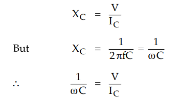
Capacitance required to improve p.f., C
= IC / ωV
Let us understand the power factor
improvement with the help of power triangle shown in the Fig. 7.22.2 For p.f.
cos ϕ, the power triangle is OXZ while for improved p.f. cos ϕ, the power
triangle is OXY. The active part of power remains unchanged. But the lagging
kVAR of load is reduced by capacitor to enhance the p.f. from cos ϕ ' to cos ϕ.
Leading kVAR supplied by capacitor = YZ

= XZ - XY = kVAR1 - kVAR
= OX tan ϕ ' – OX tan ϕ
= OX(tan ϕ ' – tan ϕ)
= kW (tan ϕ ' - tan ϕ)
With the knowledge of leading kVAR
supplied by capacitor, other results can be obtained.
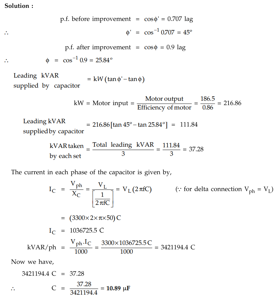
Example 7.22.1
A 3 phase, 50 Hz, 3300 V star connected induction motor develops 250 hp
(186.5 kW), the power factor being 0.707 lagging and the efficiency 0.86. Three
capacitors in delta are connected across the supply terminals and power factor
raised to 0.9 lagging. Calculate
i) The kVAR rating of the capacitor bank
ii) The capacitance of each unit

Solution :
Example 7.22.2
A 3 phase, 50 Hz, 3000 V motor develops 447.6 kW, the p.f. being 0.75
lagging and the efficiency 0.93. A bank of capacitors is connected in delta
across the supply terminals and p.f. raised to 0.95 lagging. Each of the
capacitance units is built of five similar 600 V capacitors. Determine the
capacitance of each capacitor.
Solution :
p.f. before improvement = cos ϕ ' = 0.75
lag ϕ ' = cos-1 0.75 = 41.40°
tan ϕ ' = tan 41.40° = 0.8819
p.f. after improvement = cos ϕ = 0.95
lag ϕ = cos-1 0.95 = 18.19°
tan ϕ = tan 18.19° = 0.3286
kW = Motor input = Motor output /
Efficiency = 447.6 / 0.93 = 481.29 kW.

Transmission and Distribution: Unit V: (a) Distribution Systems : Tag: : Distribution Systems - Power Factor Correction Calculation
Related Topics
Related Subjects

Transmission and Distribution
EE3401 TD 4th Semester EEE Dept | 2021 Regulation | 4th Semester EEE Dept 2021 Regulation