Transmission and Distribution: Unit V: (a) Distribution Systems
Power Factor Improvement
Importance of
Questions : 1. Explain the concept of power factor improvement. 2. Comment of the imporance of power factor improvement.
Power Factor Improvement
The low power factor is mainly because
of a.c. motors which are of induction type having low lagging power factor.
Similarly lighting load, arc lamps, electric discharge lamps, industrial
induction furnaces etc. also contribute to low power factor operation. To
improve the power factor, it is necessary to connect some device which takes
leading power to neutralize lagging effect. One of such devices is a capacitor
which draws a leading current. Let us see the action of capacitor in a power
factor improvement.
Consider a lagging power factor load as
shown in the Fig. 7.20.1 (a). The corresponding phasor diagram is shown in the
Fig. 7.20.1 (b).

Let I1 be the current drawn
at a lagging power factor angle of ϕ1
Now to improve the power factor, a
capacitor is connected across the load as shown in the Fig. 7.20.2.

Now the capacitor takes a leading
current I2, which leads voltage V by an angle of 90° as shown in the
Fig. 7.20.3 (a). Now this leading component of current 12 tries to neutralise
the lagging effect of I p Hence the resultant current becomes in the Fig.
7.20.3 (b).

Now from the Fig. 7.20.3 (b), it can be seen that the efective power factor angle becomes ϕ which is less than ϕ1 Hence cos ϕ is more than cos ϕ1 thus there is improvement in the power factor of the system. Thus by connecting a leading power factor device, across the supply power factor can be improved which is advantageous from the supplier as well as consumer point of view.
It can be seen from above phasor diagram
that the resultant current I drawn by circuit from supply after connecting
capacitor in parallel is less than that of circuit current I1 without
capacitor in circuit.
The active or wattful component remains
same after and before power factor improvement because the capacitor only
reduces the reactive component. Active power also remains unchanged
I1cos ϕ = I cos ϕ
VI1cos ϕ = VI cos ϕ
The reactive component which is lagging
reduces after power factor improvement. Its value equal to difference between
reactive component of load and capacitor current I2
I sin ϕ = I1 sin ϕ - I2
Multiplying both sides of above equation
by V
VI sin ϕ = VI1 sin ϕ - VI2
The capacitor current leads the supply
voltage by 90°
ϕc = 90°
sin ϕc = sin 90° = 1
Leading kVAR supplied by capacitor = VI2
sin ϕc = VI2 sin 90° = VI2
, kVAR after power factor improvement = Lagging
kVAR before power factor improvement - Leading kVAR supplied by capacitor
1. Importance of Power Factor Improvement
The improvement in power factor is
important for both consumers and generating stations.
The industrial and other large consumers
pay electricity charges based on maximum demand in kVA in addition to units
actually consumed. With improvement in power factor there is corresponding decrease
in maximum demand as
Maximum demand (in kVA) = Peak load ( kW ) / cos ϕ
Due to reduction in maximum demand, the
demand charges can be saved by the consumers annually. Thus there is net saving
for the consumer if the p.f. is maintained at proper value even though p.f.
improvement device requires an extra cost.
Additionally consumers can get incentive
or discount in their electricity bills if they maintain power factor closer to
unity.
The power factor consideration is
important for generating stations also. The alternators in power stations are
having rating in kVA while their useful output depends upon kW output supplied.
Now, output in kW = kVA × cos ϕ
The more the p.f., the output of station
is more and higher are the units (kWh) supplied by that station to the system.
This helps in improving the revenue obtained from that station. Thus improved
p.f. enhances earning capacity of generating station.
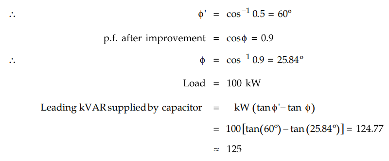
Example 7.20.1
What should be the kVA rating of a capacitor which would raise the power
factor of load of 100 kW from 0.5 lagging to 0.9 lagging
Solution : p.f.
before improvement = cos ϕ = 0.5
The capacitor is assumed to operate at p.f.
angle of 90° means the phase angle between voltage and current is 90° then sin
90° = 1( ϕc = p.f. angle of capacitor = 90°)
We have, kVAR = kVA sin ϕc
kVA = kVAR / sin ϕc = 125 / 1 = 125
kVA rating of capacitor = 125
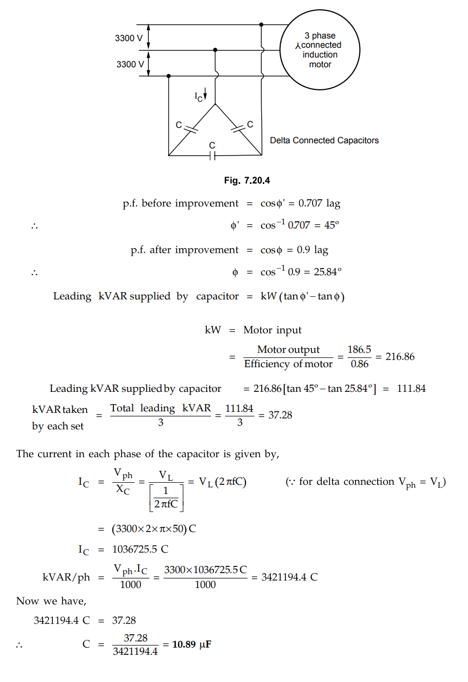
Example 7.20.2
A 3 phase, 50 Hz, 3500 V star connected induction motor develops 250 hp
(186.5 kW), the power factor being 0.707 lagging and the efficiency 0.86. Three
capacitors in delta are connected across the supply terminals and power factor
raised to 0.9 lagging. Calculate i) The kVAR rating of the capacitor bank ii)
The capacitance of each unit
Solution :
Example 7.20.3 A
3 phase, 50 Hz, 3000 V motor develops 447.6 kW, the p.f. being 0.75 lagging and
the efficiency 0.93. A bank of capacitors is connected in delta across the
supply terminals and p.f. raised to 0.95 lagging. Each of the capacitance units
is built of five similar 600 V capacitors. Determine the capacitance of each
capacitor.
Solution :

Review Questions
1. Explain the concept of power factor improvement.
2. Comment of the imporance of power factor improvement.
Transmission and Distribution: Unit V: (a) Distribution Systems : Tag: : Importance of - Power Factor Improvement
Related Topics
Related Subjects

Transmission and Distribution
EE3401 TD 4th Semester EEE Dept | 2021 Regulation | 4th Semester EEE Dept 2021 Regulation