Electron Devices and Circuits: Unit V: (b) Oscillators
RC Phase Shift Oscillator
• It consists of an amplifier and feedback network consisting of resistors and capacitors.
RC Phase Shift Oscillator
AU
: May-06, 11, 14, 16, 17, Dec.-ll, 12, 14, 16, 17, 18
•
It consists of an amplifier and feedback network consisting of resistors and
capacitors.
•
An amplifier can be BJT, FET or operational amplifier.
1. Analysis of RC Circuit
The
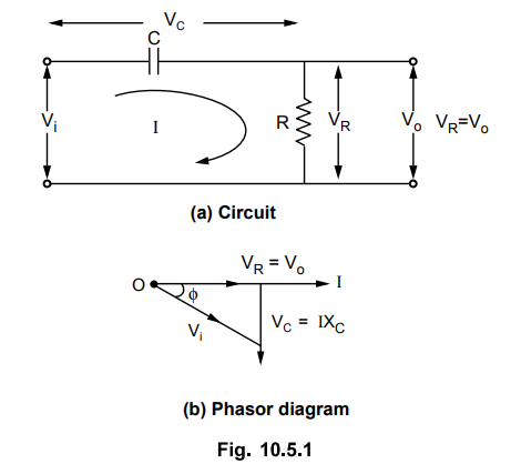
Fig. 10.5.1 (a) shows basic RC network. The output is taken across resistor R.
•
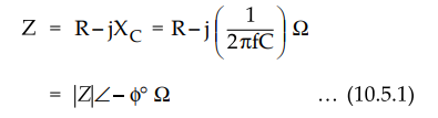
The capacitive reactance XC is given by XC = 1 / 2πfC Ω
where f is frequency of the input.
•
The total impedance of the circuit is,
•
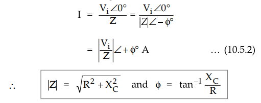
The current I flowing in the circuit is, ViZ0° _ ViZ0°
•
The equation (10.5.2) shows that current I leads input voltage by angle ϕ
•
The output voltage is drop across R hence
Vo
= VR = IR ...
(10.5.3)
•
The output voltage is in phase with current hence it leads input voltage by
angle ϕ
•
Thus R-C circuit introduces a phase shift ϕ between input and output which
depends on R, C and frequency f.
2. RC Feedback Network for Phase Shift
•
In RC phase shift oscillator, amplifier introduces a phase shift of 180°.
•
Thus the feedback network must introduce a phase shift of 180° to satisfy
Barkhausen condition.
•
The RC feedback network consists of three RC sections, with each RC section
contributing 60° phase shift.
•
Hence in RC phase shift oscillator, the feedback network consists of three RC
sections, as shown in the Fig. 10.5.2.

•
In all the three sections, resistance values and capacitance values are same so
that at a particular frequency, each section produces precisely 60° phase
shift. This is operating frequency of oscillator.
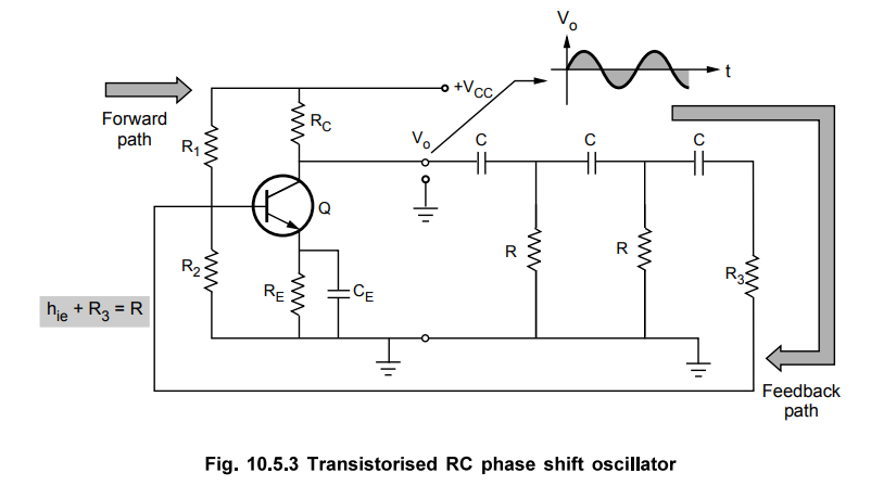
3. Transistorised RC Phase Shift Oscillator
•
The Fig. 10.5.3 shows RC phase shift oscillator which uses BJT amplifier stage
which is single stage amplifier in common emitter configuration.
•
A phase shift network has three RC sections.
•
The output of CE amplifier is connected as input to the RC phase shifting
network.
•
The output of RC phase shifting network is connected as input to the amplifier.
•
Due to common emitter amplifier it introduces a phase shift of 180° between its
input and output.
•
The RC phase shift network contributes further 180° phase shift so that phase
shift around a loop is 360°.
•
From the Fig. 10.5.3, neglecting R1 and R2 we can write,
hie
= Input impedance of the amplifier stage
•
Thus to have all three resistance values in three RC sections equal, resistance
in the last section is selected as R3 so that R3 + hie
= R.

•
When gain A of the amplifier stage and feedback factor β are adjusted to give
|A β
| = 1, then the circuit works as an oscillator, satisfying both the Barkhausen
conditions.
4. Derivation of Frequency of Oscillations
•
Replacing the transistor by its approximate h-parameter model, the equivalent
circuit of RC phase shift oscillator is as shown in the Fig. 10.5.4
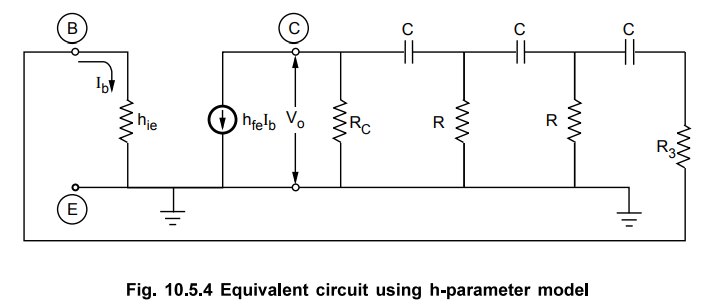
•
It is known that R = hie + R3 and replace current source
by equivalent voltage source.
•
The ratio of resistance RC to R is k.
RC
/ R = k
•
The modified equivalent circuit is as shown in the Fig. 10.5.5.
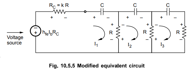
•
Applying KVL to the three loops,
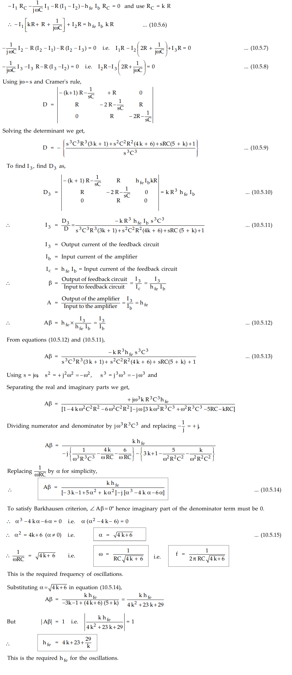
5. Minimum Value of hfe
For
satisfying Aβ = 1, the expression for the value of hfe of the
transistor used in RC phase shift oscillator is given by,
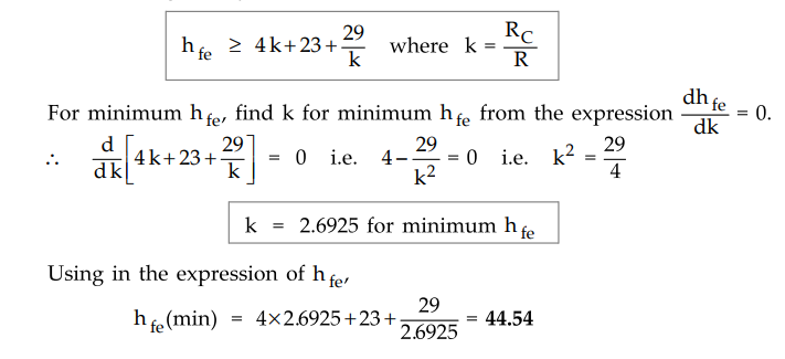
Thus
for the circuit to oscillate, the transistor must be selected with hfe
greater than 44.54.
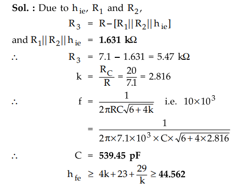
Ex.
10.5.1 Find the capacitor C and /yg for the transistor to provide a resonating
frequency of 10 kHz of a transistorised phase shift oscillator. Assume R1 =25
kΩ, R2 =57kΩ RC = 20Ω,
R = 7.1kΩ and hie = 1.8kΩ
Sol.
:
6. Advantages of RC Phase Shift Oscillator
•
The advantages of R-C phase shift oscillator are,
1.
The circuit is simple to design.
2.
Can produce output over audio frequency range.
3.
Produces sinusoidal output waveform.
4.
It is a fixed frequency oscillator.
7. Disadvantages of RC Phase Shift Oscillator
1.
To vary the frequency, values of R and C of all three sections are to be varied
simultaneously which is practically difficult. Hence frequency can not be
varied.
2.
Frequency stability is poor due to changes in the values of various components
due to effect of temperature, aging etc.
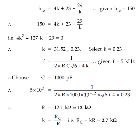
Ex.
10.5.2 Design a RC phase shift oscillator to generate 5 kHz sine wave with 20 V
peak to peak amplitude. Draw the designed circuit. Assume hfe = 150.
Sol.
:
For RC phase shift oscillator,
•
Neglecting effect of biasing resistances assuming them to be large and
selecting transistor with hie = 2 kΩ ,
Ri
= 2 kΩ
Last
resistance in phase shift network
R3
= R - Ri = 12 - 2 = 10 kΩ
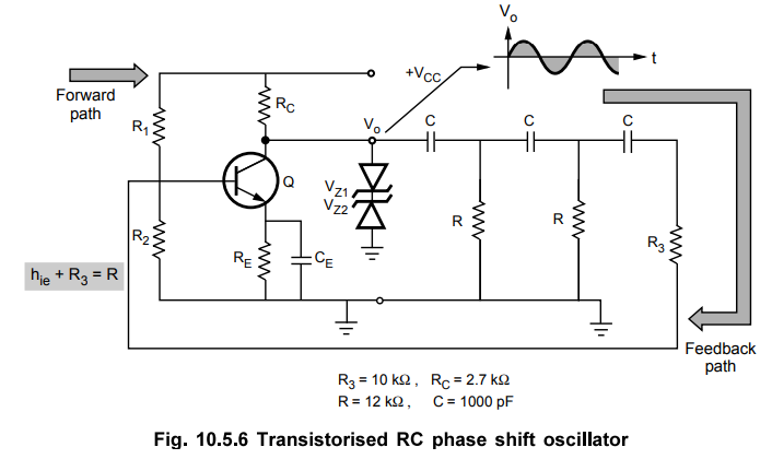
•
Using the back to back connected zener diodes of 9.3 V (Vz) each at the output of emitter follower and using
this at the output of the oscillator, the output amplitude can be controlled to
10 V i.e. 20 V peak to peak. The zener diode 9.3 V and forward biased diode of
0.7 V gives total 10 V.
•
The designed circuit is as shown in the Fig. 10.5.6.
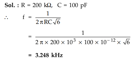
Ex.
10.5.3 In an RC phase shift oscillator, if R1 = R2 =R3
=200kΩ and C1 =C2 = C3 =100 pF. Find the
frequency of the oscillator.
Sol.
:
R = 200 kΩ, C = 100 pF
Ex.
10.5.4 Design a RC phase shift oscillator to generate 5 kHz sine wave with 20 V
peak to peak amplitude. Assume hfe = β = 150, C = 1.5 nF, hie
= 1.2 kΩ.
Sol.
:
Refer Ex. 10.5.2 for the procedure and verify the values as :
R
= 8.06 kΩ , RC = 1.86 kΩ, R3 = 6.86 kΩ.
Review Questions
1. With a neat diagram, explain the construction and working of
BJT RC phase shift oscillator.
AU : Dec.-ll, 12, 14, 18, May-16, 17. Marks 8
2. Find C and hfe of a transistor to provide a
resonating frequency of 10 kHz of a transistor phase shift oscillator. R1
= 24 kΩ, R2 = b8 kΩ, RC = 18 kΩ, R = 6.8 kΩ = and hie
= 2 kΩ.
(Ans.: 575 pF ≥ 44.543)
3. State the advantages and disadvantages of RC phase shift
oscillator.
4. Derive the expression for the frequency of oscillations of RC
phase shift oscillator. Hence obtain the expression of amplifier gain required
for the oscillations.
AU : May-14, 16, Marks 8
5. Design an oscillator to operate at a frequency of 10 kHz
which gives an extremely pure sine wave output, good frequency stability and
highly stabilized amplitude. Discuss the operation of this oscillator as an
audio signal generators.
AU : May-17, Marks 15
6. Explain the working of a phase shift oscillator. Discuss its
advantages and disadvantages.
AU : Dec.-17, Marks 8
7. Explain the working of phase shift oscillator.
Electron Devices and Circuits: Unit V: (b) Oscillators : Tag: : - RC Phase Shift Oscillator
Related Topics
Related Subjects

Electron Devices and Circuits
EC3301 3rd Semester EEE Dept | 2021 Regulation | 3rd Semester EEE Dept 2021 Regulation