Microprocessors and Microcontrollers: Unit I: (c) 8085 Timing Diagrams
Representation of Signals
Questions : 1. What is clock signal ? 2. Show the representation of single signal. 3. Show the representation of group of signals.
Representation of Signals
Before
going to see the timing diagram, we will see the signals and its representation
used in the timing diagrams.
Clock
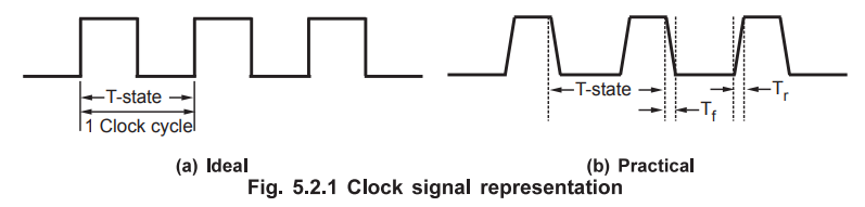
Signal : The 8085 divides the clock frequency provided at x
1 and x2 inputs by 2, which is called operating frequency. All the operations
within the 8085 are synchronized with this operating frequency. Therefore in
the timing diagram operating frequency clock is shown on the top and then the
signals are shown with reference to operating frequency clock. Ideally, the
clock signal should be square wave with zero rise time and fall time, as shown
in the Fig. 5.2.1. But in practice, we do not get zero rise time and fall time.
Therefore the clock and other signals are always shown with finite rise and
fall times. Fig. 5.2.1 shows the practical way of representing clock signal.
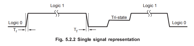
Single
Signal : Single signal is represented by a line. It may have
status either logic 0 or logic 1 or tri-state. The change in the state of the
signal takes finite time and hence the state change of signal is represented
with finite rise time and fall time, as shown in the Fig. 5.2.2.
Group
of Signals :
Group
of signals is also called a bus e.g. address bus and data bus. To avoid
complications in the timing diagram these signals are grouped and shown in the
form of block as shown in Fig. 5.2.3.
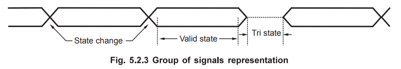
In
the group representation individual state is not considered, but the group
state is considered. Change in state of single signal changes the state of
group. It is represented by the cross as shown the Fig. 5.2.3. The tri-state
condition of the group signals is shown by dotted lines. Two straight lines
represent valid state/stable state.
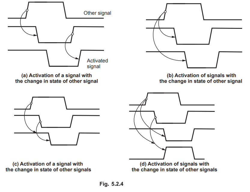
In
microprocessor systems, activation of signal/signals depends on the state of
other signal/signals. Such situations are shown in the timing diagrams with the
help of specific symbols. There are four possibilities :
Activation
of a signal with the change in state of other signal.
Activation
of a signal with the change in state of other signals.
Activation
of signals with the change in state of other signal.
Activation
of signals with the change in state of other signals.
Fig.
5.2.4 shows the representation of dependence of the signal/signals, in the
timing diagram.
Review Questions
1. What is clock
signal ?
2. Show the
representation of single signal.
3. Show the representation of group of signals.
Microprocessors and Microcontrollers: Unit I: (c) 8085 Timing Diagrams : Tag: : - Representation of Signals
Related Topics
Related Subjects
Microprocessor and Microcontroller
EE3404 MCU 4th Semester EEE Dept | 2021 Regulation | 4th Semester EEE Dept 2021 Regulation