Digital Logic Circuits: Unit I: (b) Digital Logic Families
Resistor - Transistor Logic (RTL)
Circuit, Operation, Truth table, Specifications, Connection
• We begin our discussion of logic gates by considering the Resistor-Transistor-Logic (RTL) gate. Although RTL has become obsolete now, because of its simplicity and for historical reasons, it is proper to devote some attention to it and develop concepts useful in connection with all types of gates.
Resistor - Transistor Logic (RTL)
•
We begin our discussion of logic gates by considering the
Resistor-Transistor-Logic (RTL) gate. Although RTL has become obsolete now,
because of its simplicity and for historical reasons, it is proper to devote
some attention to it and develop concepts useful in connection with all types
of gates.
1. RTL Circuit
•
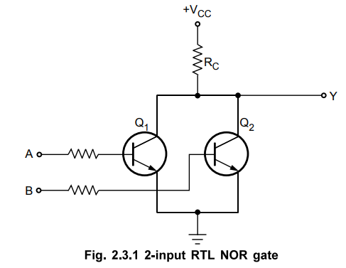
RTL circuits consist of resistors and transistors. Fig. 2.3.1 shows 2-input RTL
NOR gate. As shown in the Fig. 2.3.1, emitters of both the transistors are
connected to a common ground and collectors of both transistors are tied
through a common collector resistor Rc to a supply voltage Vcc . The resistor
Rc is commonly known as passive pull-up resistor.
2. Circuit Operation
•
Inputs representing logic levels are applied at A and B terminals. In the RTL
gate the input voltage corresponding to LOW level is required to be low enough
for the corresponding transistor to be cut off. Similarly, the input voltage
corresponding to HIGH level should be high enough to drive the corresponding
transistor to saturation.
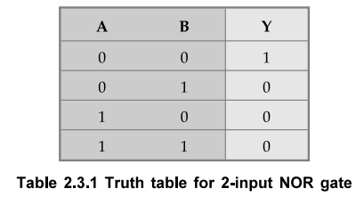
• When both the inputs are Low, transistors Q1 and Q2 are cut-off and the output is HIGH. A HIGH level on any input drives the corresponding transistor to saturation causing the output to go LOW. Table 2.3.1 shows the truth table for 2-input NOR gate.
• We know that, the saturation voltage, VCE for transistor is approximately 0.2 V. Therefore, for RTL gates the LOW level output voltage is 0.2 V. In RTL a HIGH level output voltage depends on the number of gates connected to the output. As number of gates connected to the output increases, output voltage decreases. This is the deciding factor for the fan-out of the gate. The number of gates connected to the output also affects the propagation delay time.
3. Specifications
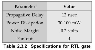
The
Table 2.3.2 gives the specifications for RTL gate.
•
From above specifications we can say that RTL gates have poor noise margin,
poor fan-out capabilities, low speed and high power dissipation.
4. Wire – AND Connection
•
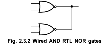
The RTL has a capacity called wire - AND. Since the output is effectively a
transistor, two outputs can be wired together. This is illustrated in Fig.
2.3.2.
Review Questions
1. Explain the operation of 2-input RTL NOR gate,
2. Write a note on RTL family.
Digital Logic Circuits: Unit I: (b) Digital Logic Families : Tag: : Circuit, Operation, Truth table, Specifications, Connection - Resistor - Transistor Logic (RTL)
Digital Logic Circuits: Unit I: (b) Digital Logic Families
Under Subject

Digital Logic Circuits
EE3302 3rd Semester EEE Dept | 2021 Regulation | 3rd Semester EEE Dept 2021 Regulation
Related Subjects
Probability and complex function
MA3303 3rd Semester EEE Dept | 2021 Regulation | 3rd Semester EEE Dept 2021 Regulation

Electromagnetic Theory
EE3301 3rd Semester EEE Dept | 2021 Regulation | 3rd Semester EEE Dept 2021 Regulation
Digital Logic Circuits
EE3302 3rd Semester EEE Dept | 2021 Regulation | 3rd Semester EEE Dept 2021 Regulation

Electron Devices and Circuits
EC3301 3rd Semester EEE Dept | 2021 Regulation | 3rd Semester EEE Dept 2021 Regulation

Electrical Machines I
EE3303 EM 1 3rd Semester EEE Dept | 2021 Regulation | 3rd Semester EEE Dept 2021 Regulation
C Programming and Data Structures
CS3353 3rd Semester EEE, ECE Dept | 2021 Regulation | 3rd Semester EEE Dept 2021 Regulation