Transmission and Distribution: Unit V: (a) Distribution Systems
Schemes of Distribution System
Radial - Ring Main - Interconnected
Questions : 1. Explain radial distribution system in detail. 2. Explain about ring main distribution system. State its advantages. 3. Explain ring main distribution with interconnector. 4. Explain the interconnected system of distribution. State its advantages. 5. Discuss and compare radial and ring main distribution systems. What is the role of interconnectors ?
Schemes of Distribution
System
AU : May-07, 12, 16, 17, Dec.-05, 07,
09, 10, 12, 13
The various schemes of distribution
system are,
i) Radial distribution system
ii) Ring main distribution system
iii) Ring main distribution system with
interconnector
iv) Interconnected system
1. Radial Distribution System
The Fig. 7.6.1 shows a radial
distribution system.
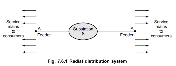
When the distributor is connected to
substation on one end only with the help of feeder, then the system is called
radial distribution system. The feeders, distributors and service mains are
radiating away from the substation hence name given as radial system. There are
combinations of one distributor and one feeder, connecting that distributor to
the substation. In the Fig. 7.6.1, distributor 1 is connected only at one end
to substation through a feeder at point A. Similarly the other feeder is
feeding the distributor 2, only at one point B.
Due to such system, if the fault occurs
either on feeder or a distributor, all the consumers connected to that
distributor will get affected. There would be an interruption of supply to all
such consumers. Similarly the end of the distributor nearer to the substation
will get heavily loaded than the end which is too far away from the substation.
Similarly the consumers at the distant end of the distributor would be
subjected to the voltage variations and fluctuations, as the load on the
distributor changes. The system is advantageous only when the generation is at
low voltage level and the substation is loaded at the centre of the load.
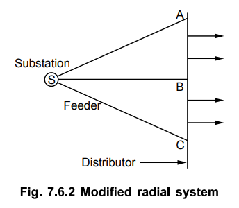
The fault on a feeder or a distributor
causes interruption in supply to all the consumers connected to the
distributor. This can be avoided by modifying the radial system as shown in the
Fig. 7.6.2. In this system, the distributor is fed at number of points with the
help of feeders. In Fig. 7.6.2, the feeders from the substation are feeding to
a single distributor at points A, B and C.
a. Advantages of Radial System
The various advantages of radial system
are,
1. Simplest as is fed at only one end.
2. The initial cost is low.
3. Useful when the generation is at low
voltage.
4. Preferred when the station is located
at the centre of the load.
b. Disadvantages of Radial System
Apart from its advantages, this system
is suffered from the following disadvantages,
1. The end of distributor near to the
substation gets heavily loaded.
2. When load on the distributor changes,
the consumers at the distant end of the distributor face serious voltage
fluctuations.
3. As consumers are dependent on single
feeder and distributor, a fault on any of these two causes interruption in
supply to all the consumers connected to that distributor.
2. Ring Main Distribution System
Another system of distribution which
eliminates the disadvantages of the radial system is used in practice called
ring main
In such system, the feeder covers the
whole area of supply in the ring fashion and finally terminates at the
substation from where it is started. The feeder is in closed loop form and looks
like a ring hence the name given to the system as ring main system. This is
shown in the Fig. 7.6.3.
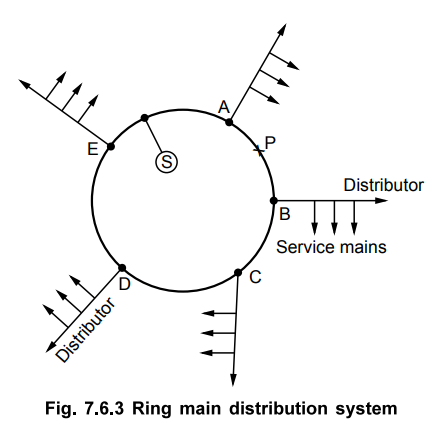
The feeder in the ring fashion is
divided into number of sections as AB, BC, CD, DE and EA. The various
distributors are connected at A, B, C, D and E. Each distributor is supplied by
the two feeders and hence the design is similar to the two feeders in parallel
on different paths.
Hence if there is any fault on any part
of the feeder, still the consumers will keep on getting the continuous supply.
For example, if the fault occurs at point P in the section AB of the feeder,
still the consumers connected to the distributors at A and B will get supply
from the sound feeder sections AE and BC. The part AB of the feeder can be
isolated and repaired. The feeder can be fed at one or more feeding points.
Thus the disadvantages of radial system are eliminated in this system. The
great saving in copper is another major advantage of the ring main system.
a. Advantages of Ring Main Distribution
System
1. The feeders get equally loaded.
2. If fault develops on one of the
feeders then consumer gets continuous supply from the other part of the feeder.
3. It eliminates the possibility of the
voltage fluctuations.
4. Easy from the maintenance and repair
point of view without interrupting the supply to the consumers.
5. Great saving in copper required.
3. Ring Main Distributor with Interconnector
It has been mentioned that in ring main
system, the cable is arranged in the loop or ring fashion. In most simple case,
the ring distributor is fed at only one point.
But sometimes the ring main system is
used to supply a large area and hence voltage drop across the various sections
may become large in such case. Hence to compensate for such excessive voltage
drops, the distant points of ring distributor are joined together by a
conductor. This is called an interconnector. The Fig. 7.6.4 shows a ring main
system with an interconnector.
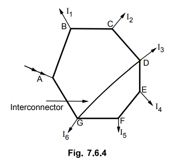
The points D and G are joined by an
interconnector.
Such a case is generally analysed using
Ihevenin's theorem.
Let us briefly revise the steps to use
the Thevenin's theorem.
The steps to use Thevenin's theorem :
1. Remove an interconnector DG.
2. Find the voltage VDG
without an interconnector, which is Thevenin's voltage denoted as Eo.
3. Determine the equivalent resistance
as viewed through the terminals D and G, i.e. where an interconnector is to be
connected. This is Thevenin's equivalent resistance denoted as RTH.
4. Knowing the resistance of an
interconnector DG, the Thevenin's equivalent can be drawn as shown in the Fig.
7.6.5.
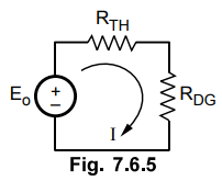
5. The current I through an
interconnector then can be obtained as,
I = (Eo / RTH + RDG)
amp
Once this current is known, current in
all the sections and the voltages at load points can be determined.
Example 7.6.1
A 2 wire d.c. ring main is fed at A and load is tapped at points B, C and D.
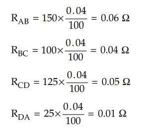
The distributor length is 400 m long and points B, C and D are 150 m, 250 m and
375 m from point A. The loads are 150 A, 40 A and 200 A respectively. If the
resistance per 100 m of single conductor is 0.04 Ω and voltage at feeding point
A is 240 V, calculate: 1. Current in each section of distributor 2. Voltages at
points B, C and D.
Solution:
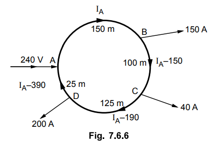
The distributor is shown in the Fig. 7.6.6.
The resistances of various sections are,
Let IA be the current flowing
through section AB, so other currents in various sections are as shown in the
Fig. 7.6.6.
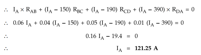
Applying KVL, total voltage drop along
loop is zero.
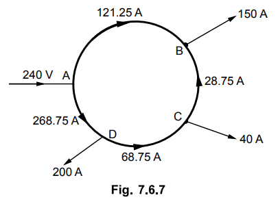
Hence the actual distribution of
currents are as shown in the Fig. 7.6.7.
The negative sign of current in any
section indicates that the actual direction of flow of current is opposite to
what is assumed.
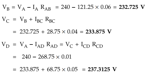
The various voltages are,
It can be seen that, point B is the
point of minimum potential and is fed by currents in both the directions as
shown in the Fig. 7.6.7.
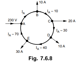
Example 7.6.2
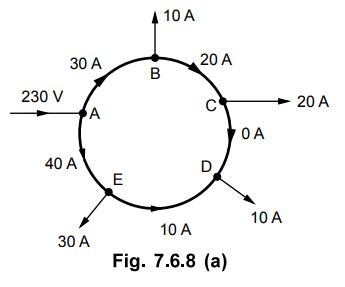
A two wire dc ring main distributor ABCDEA is fed at point A with 230 V supply.
The resistances of go and return conductors of each section AB, BC, CD, DE, AE
are 0.1 ohm. The main supplies the loads of 10A at B, 20A at C, 10A at D, 30A
at E. Find the voltage at each load point.
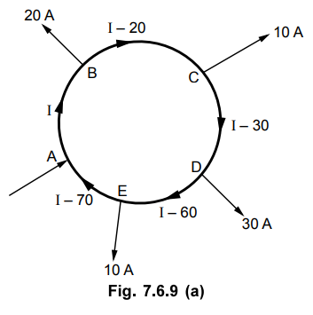
Ans. :
The distributor is shown in the Fig.
7.6.8.
RAB = RBC = RCD
= RDE = RAE = 01Ω
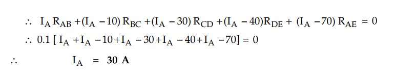
Applying KVL, the total voltage drop
along the loop is zero.
The actual current distribution is as
shown in the Fig. 7.6.8 (a)
The negative sign of the current in any
section indicates that the actual direction of flow of current is opposite to
what is assumed. The voltage at each load point is,
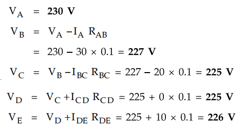
Example 7.6.3 The
Fig. 7.6.9 shows a ring distributor with interconnector BD. The supply is fed
at point A. The resistances of all the sections are indicated in the Fig.
7.6.9.
Calculate : 1. Current in the
interconnector 2. Voltage drop in the interconnector
Solution:
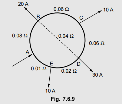
Use the Thevenin's theorem. Remove the interconnector BD.
The current in section AB is I A. So
other currents are as shown in the Fig. 7.6.9 (a). The total voltage drop
around a loop is zero.
The negative sign indicates that current
ICD flows from D to C and not from C to D.
The drop BCD = IBC RBC
+ ICD × RCD = 1.304 × 0.06 - 8.695 × 0.06 = - 0.4435 V
This is Thevenin's voltage Eo
and B is - ve w.r.t. D, as indicted by negative sign.
Eo = 0.4435 V
Now calculate RTH as viewed through the
terminals BD.
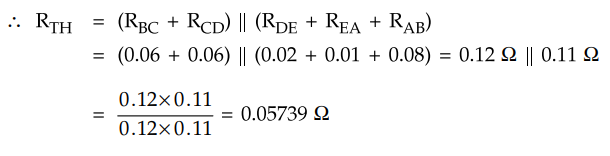
Hence the Thevenin's equivalent is as
shown in the Fig. 7.6.9(b).
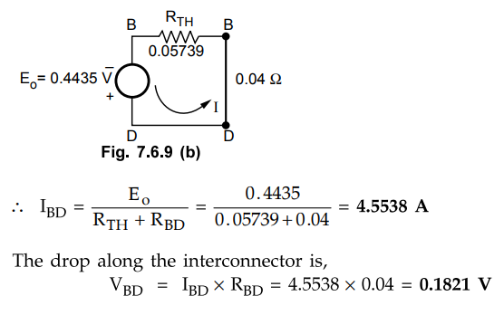
The drop along the interconnector is,
VBD = IBD × RBD
= 4.5538 × 0.04 = 0.1821 V
4. Interconnected Distribution System
When a ring main system is supplied by
two or more than two generating stations then it is called interconnected
system.
The Fig. 7.6.10 shows the single line
diagram of an interconnected system.
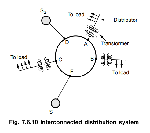
The closed ring is supplied from two
sources S1 and S2 at points E and D respectively. The
distributors are connected at the points A, B and C, through distribution
transformers. The advantages of such an interconnected system are,
1. Reliability of supply increases, continued
with the help of other In case of fault on one source, supply can be sources.
2. Additional load demand in one area
can be fed from other source where load demand is less. This reduces the
reserve power capacity and improves the efficiency of the distribution system.
Review Questions
1. Explain radial distribution system in detail.
AU May-07, Dec.-lO, 13, Marks 8
2. Explain about ring main distribution system. State its
advantages.
AU : Dec -05, 10, 12, 13, May-12, Marks 8
3. Explain ring main distribution with interconnector.
AU : May-07, Dec.-09, 10, 13, Marks 8
4. Explain the interconnected system of distribution. State its
advantages.
AU : Dec.-13, May-17, Marks 4
5. Discuss and compare radial and ring main distribution systems.
What is the role of interconnectors ?
AU : Dec.-07, May-17, Marks 4
6. A ring distributor is loaded as shown in the Fig. 7.6.11. The
resistances indicated are for go and return both.
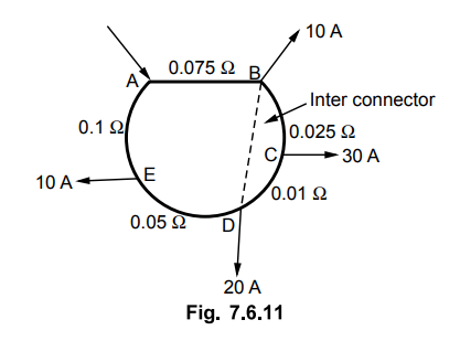
a. Current in the interconnecter b. Drop in the interconnector.
[Ans.: 9.8 A, 0.49 V]
7. A DC ring main A, B, C, D, A is fed from point A from 250 V supply
and resistance (including go and return) cf various sections are given below.
AB = 0.2 ohms, BC = 0.018 ohms, CD = 0.025 ohms and DA = 0.02 ohms.
The main supplies a load of 150 A, at B, 300 A at C and 250 A at D.
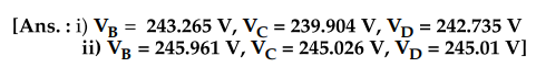
i) Determine the voltage at each load point.
ii) If the points A and C are linked through an inter connected of resistance
0.02 ohms, determine the new voltage at each point.
8. The points B and D of a D.C. ring main ABCDEA are linked through
an inter connector. The supply is given at point A. The resistance of go and
return conductors cf various sections are as shown in Fig. 7.6.12. Calculate
i) Current in the interconnector
ii) Voltage drop in interconnector.
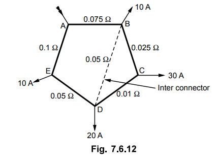
[Ans.: 9.7705 A, 0.488 V]
Transmission and Distribution: Unit V: (a) Distribution Systems : Tag: : Radial - Ring Main - Interconnected - Schemes of Distribution System
Related Topics
Related Subjects

Transmission and Distribution
EE3401 TD 4th Semester EEE Dept | 2021 Regulation | 4th Semester EEE Dept 2021 Regulation