Digital Logic Circuits: Unit III: (b) Analysis & Design of Synchronous Sequential Circuits
Sequence Detector
Analysis and Design of Synchronous Sequential Circuits
• The specified input sequence can be detected using a sequential machine called sequence detector.
Sequence Detector
•
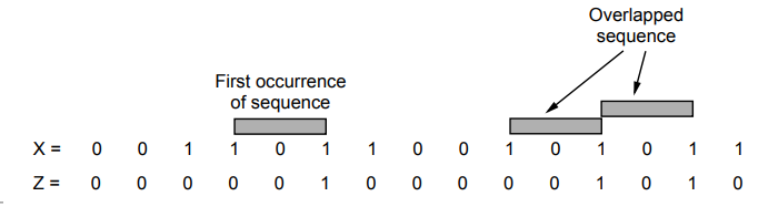
The specified input sequence can be detected using a sequential machine called
sequence detector. In this circuit output goes high when a prescribed input
sequence occurs. A typical input sequence and the corresponding output sequence
for desired input sequence 101 are :
Step
4 :
K-map simplification
Step 5 : Logic diagram
• As shown above the detection of required input sequence can occur in a longer data string and the desired input sequence can overlap with another input sequence. It is assumed that input can change only between clock pulses. Once we know the sequence which is to be detected, we can draw the state diagram for it. Then from the state diagram we can design the circuit. It is possible to implement sequence detector using both types of sequential machines Mealy machine and Moore machine. The following examples illustrate how to determine the state diagram from the given input sequence and then implement the sequence detector. Illustrative Examples
Illustrative
Examples
Ex.
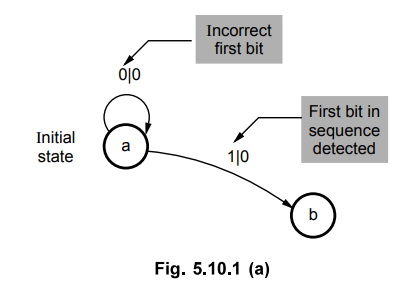
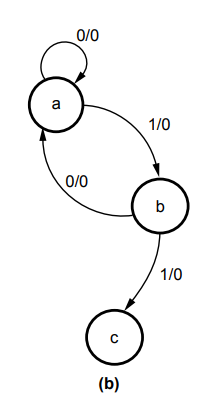
5.10.1 Design a Mealy type sequence detector to detect a serial input sequence
of 101.
Sol.
: In
a Mealy type design, the number of states in the state diagram are equal to the
number of bits in the desired input sequence. In this example, we have three
bits in the sequence so we have three states in the state diagram. Once the
number of states are known we have to draw the direction lines with states of
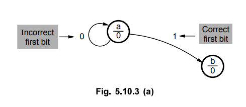
inputs and outputs. Let us start drawing direction lines, assuming state 'a' as
an initial state.
1.
State a
State
a checks for 1. When input is 1, we have detected the first bit in the
sequence, hence we have to go to the next state to detect the next bit in the
sequence.
When
input is 0, we have to remain in the state 'a' because bit 0 is not the first
bit in the sequence. In both cases output is 0 since we have not yet detected
all the bits in the sequence.
2.
State b
When
input is 0, we have detected the second bit in the sequence, hence we have to
go to the next state to detect the next bit in the sequence. When input is 1,
we have to remain in state b because 1 which we have detected may start the
sequence. Output is still zero.
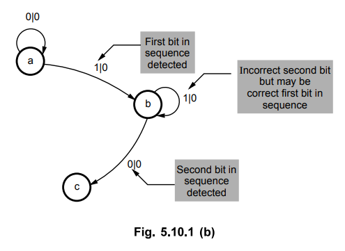
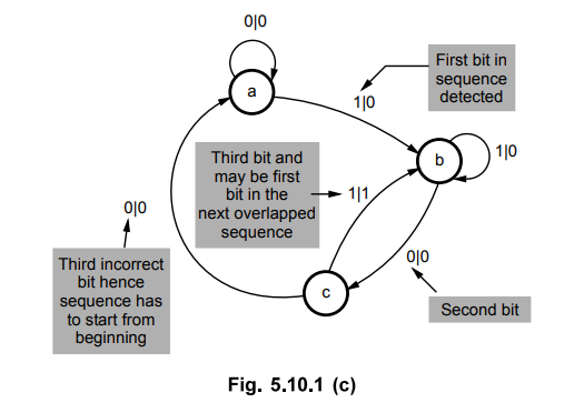
3.
State c
As
explained for state a and state b, if desired bit is detected we have to go for
next state otherwise we have to go to the previous state from where we can
continue the desired sequence. When complete sequence is detected we have to
make output HIGH and go to the initial state. This is illustrated in Fig.
5.10.1 (c).
From
the above state diagram we can determine the state table as shown in Table
5.10.1 (a).
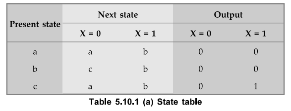
Since
there are three states we need two flip-flops. Assigning state a = 00, state b
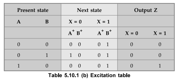
= 01 and state c = 10 we can determine the excitation table as shown in Table
5.10.1 (b).
K - map simplification
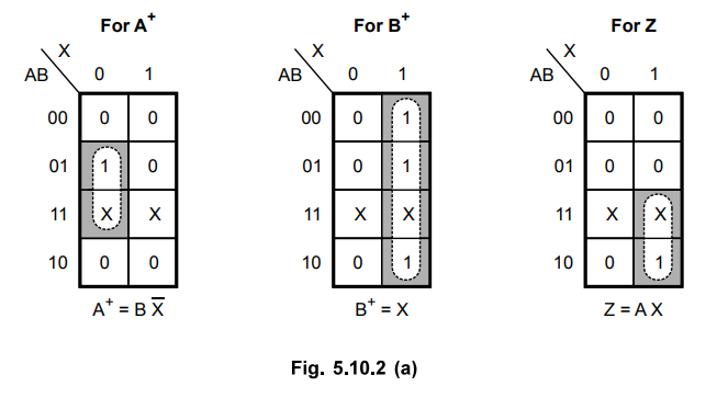
Logic diagram

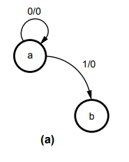
Ex.
5.10.2 Design a Moore type sequence detector to detect a serial input sequence
of 101.
Sol.
:
In a Moore type design output depends only on flip-flop states. Therefore, in
the state diagram of Moore machine, the output is written with the state
instead of with the transition between the states. Apart from this the process
of determining the state diagram is similar to that used for Mealy machine. Let
us start with state 'a' as an initial state.
1.
State a
When
input is 1, we have detected the first bit in the sequence, hence we have to go
to the next state to detect the next bit in the sequence.
When
input is 0, we have to remain in the state 'a' because bit 0 is not the first
bit in the sequence. In both cases output is 0 since we have not yet detected
all the bits in the sequence.
2.
State b
When
input is 0, we have detected the second bit in the sequence, hence we have to
go to the next state to detect the next bit in the sequence. When input is 1,
we have to remain in state b because 1 which we have detected may start the
sequence. Output is still zero.
3.
State c
Now,
when a 1 input occurs, the 101 sequence is completed and output must equal to
1. Here, we cannot go back to state b (since output in state b is zero) and
hence we have to create new state d with a output 1.
In
case if input is zero, we have to restart checking of input sequence and hence
we have to return to state a.
4.
State d
Since
the sequence is detected, this is the last state. When input is 1, we have
detected the first bit in the next sequence, hence we have to go to state b.
When input is 0, we have detected the second bit in the overlapped sequence, hence we have to go to state c.
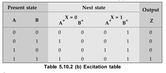
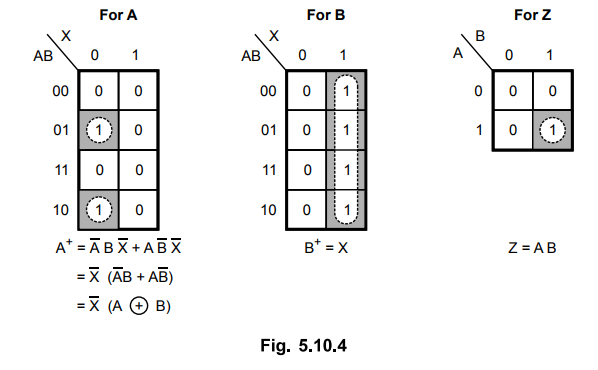
From
the above state diagram we can determine the state table as shown in Table
5.10.2 (a).
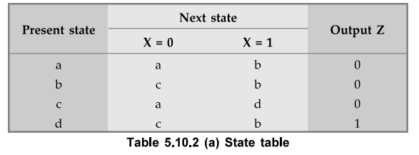
Since
there are four states we need two flip-flops. Assigning state a = 00, b = 01, c
= 10 and d = 11 we can determine the excitation table as shown in Table 5.10.2
(b).
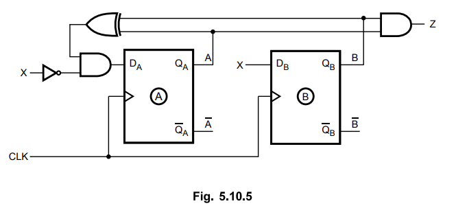
K - map simplification
Logic diagram
Examples
with Solutions
Ex.
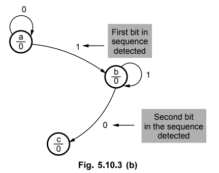
5.10.3 Design a sequence detector to detect the following sequence using JK
flip-flops. (Use Mealy Machine) ... 110
Sol.
:
The given sequence has 3-bit, so we require 3 states in the state diagram. Let
us start drawing direction lines, assuming state 'a' is an initial state.
State
a :
When
input is 1, we have detected the first bit in the sequence, hence we have to go
to the next state to detect the next bit in the sequence. When input is 0, we
have to remain in the state 'a' because bit 0 is not the first bit in the
sequence. In both cases output is 0, since we have not yet detected all the
bits in the sequence.
State
b :
When
input is 1, we have detected the second bit in the sequence, hence we have to
go to the next state to detect the next bit in the sequence. When input is 0,
we have to go to the state 'a' to detect the first bit in the sequence, i.e. 1.
State
c :
When
input is 0, we have detected the last bit in the sequence, hence we have to go
to the initial state, to detect the next sequence and make output high
indicating sequence is detected. When input is 1, we have to go to the state
'b' because 1 which we have detected may start the sequence.
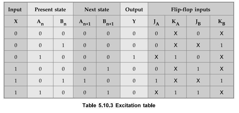
Assuming
state assignments as a = 00, b = 01 and c = 10, we can determine excitation
table for above state diagram as shown in Table 5.10.3.
K-map
simplification
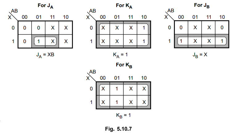
Logic diagram
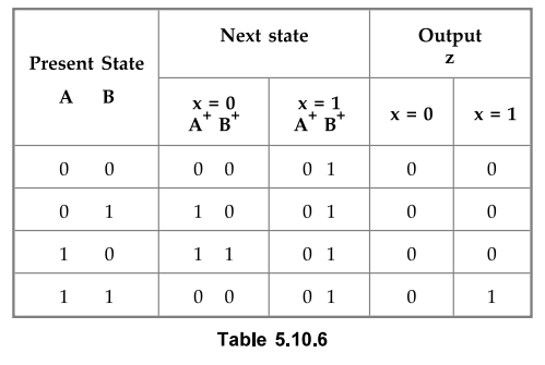
Ex.
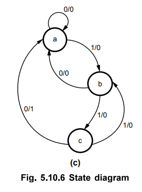
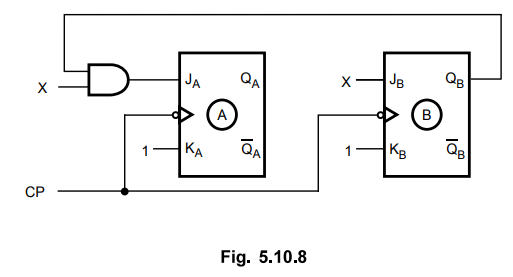
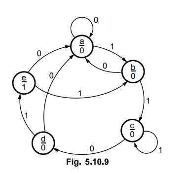
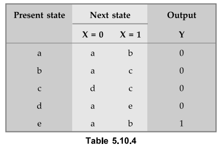
5.10.4 Design a sequence detector to detect sequence 1101.
Sol.
: State diagram
In
Moore model, output depends only on the present state and not on the input, so
state diagram is as shown in the Fig. 5.10.9.
State
table
State
assignment
a
= 000, b = 001, c = 010, d = 011 and e = 100
State
transition table
K-map
simplification
Logic diagram

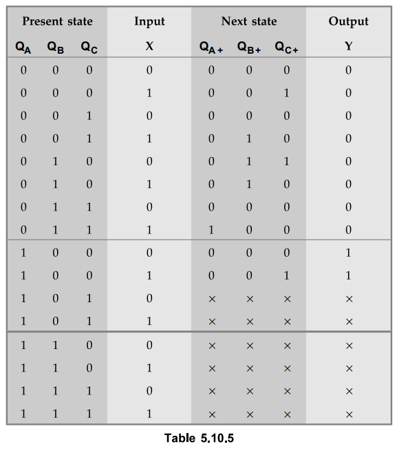
Ex.
5.10.5 Design a Mealy model of sequence detector to detect the pattern 1001.
Sol.
:
Assigning
state a = 00, b = 01, c = 10 and d = 11 we have
K-map
Simplification
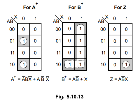
Logic diagram
Ex.
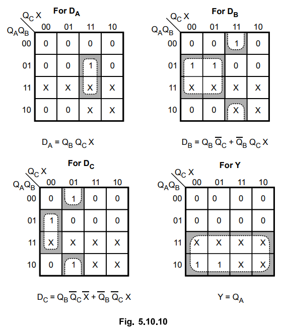
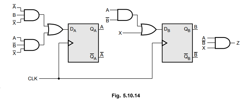
5.10.6 Design a sequence detector that produces an output 'J' wherever the non
- overlapping sequence 101101 is detected.
AU
: Dec.-16, Marks 13
Sol.
: State diagram
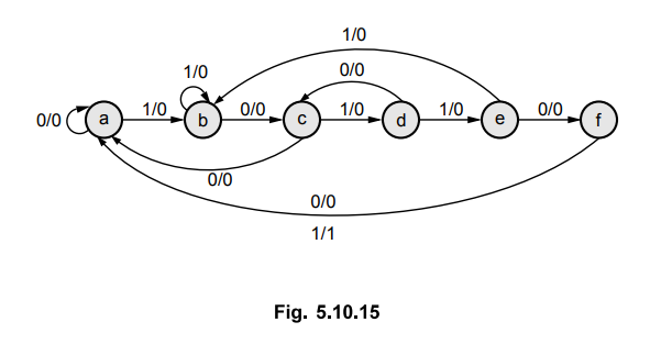
State Table
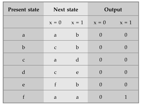
State
assignment
a
= 000, b = 001, c = 010, d = Oil, e = 100, f = 101
State
transition table
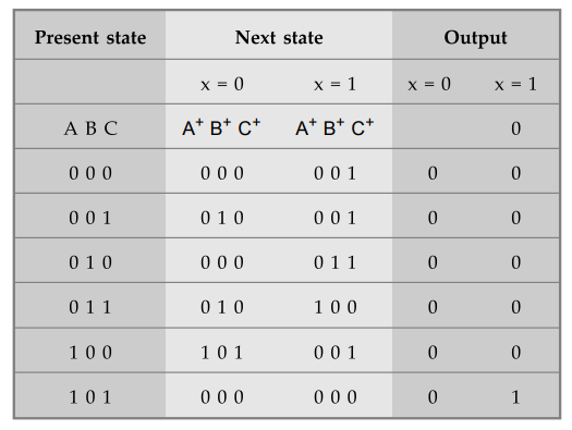
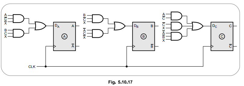
K
- map simplification - using D flip - flops
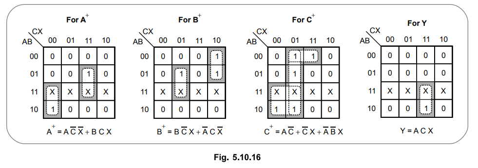
Logic
diagram
Example
for Practice
Ex.
5.10.7 Design a sequence detector which detects the sequence "OHIO"
using D flipflops (one bit overlapping).
AU
: Dec.-12, Marks 8
Digital Logic Circuits: Unit III: (b) Analysis & Design of Synchronous Sequential Circuits : Tag: : Analysis and Design of Synchronous Sequential Circuits - Sequence Detector
Related Topics
Related Subjects

Digital Logic Circuits
EE3302 3rd Semester EEE Dept | 2021 Regulation | 3rd Semester EEE Dept 2021 Regulation