Electrical Machines II: UNIT I: c. Synchronization and Parallel Operation of Alternators
Short Circuit Transients
Synchronous Generator or Alternators
The short circuit transients in a synchronous machine is a complicated phenomenon due to number of circuits coupled to each other are involve
Short Circuit Transients
It
may be possible in practice that the alternator running with full excitation
may undergo a sudden short circuit because of the abnormal conditions. Due to
sudden short circuit of alternator, large mechanical forces are developed which
may not be sustained by the alternator. These forces are proportional to square
of the current value, hence large pressure is buit up between adjacent stator
conductors.
The
short circuit transients in a synchronous machine is a complicated phenomenon
due to number of circuits coupled to each other are involved. When a
synchronous generator undergoes short circuit, it has a characteristic time
varying behaviour. During short circuit, flux per pole dynamically changes.
Thus the transients are seen in the field and damper windings. The alternator
can be represented by an equivalent circuit wherein the reactance is seen to be
changed from subtransient reactance to final steady state synchronous reactance.
When
alternator undergoes a short circuit number of events take place which depends
on various factors such as the instant in the cycle at which short circuit
occurs, whether the machine is loaded or not, what is the excitation provided,
how many phases are involved, whether it is occuring near to machine terminals
or away from it and on the constructional features of the machine. Hence the
evaluation of sudden short circuit current for the given conditions is complex
and to some extent empirical process depending on values of resistances, self
and mutural inductances which themselves are variable and difficult to assess.
After
the moment of short circuit, the time period followed by it can be divided into
three periods. The first one is very short period of one or two cycles the
conditions of which are dependent on the flux linkages between stator and rotor
during short circuit. The second interval is longer one which is nothing but
transient decay of short circuit current which is affected by damping and rise
of armature reaction. The final period is nothing but the steady state short
circuit before which the generator is normally open circuited.
1. Constant Flux Linkage Theorem
The
behaviour shown by the alternator just after short circuit can be understood by
the use of constant linkages theorem. If a closed circuit with resistance r and
inductance L is considered without a source then the equation obtained using
KVL will be This show that the flux linkages
Li remain constant. In generator also the effective inuctance of stator and
rotor windings is large compared to the resistance which can be neglected for
first few cycles. The rotor circuit is closed through exciter while stator is
closed by short circuit. Thus the flux linkag with either winding must remain
constant irrespective of the rotation.
This show that the flux linkages
Li remain constant. In generator also the effective inuctance of stator and
rotor windings is large compared to the resistance which can be neglected for
first few cycles. The rotor circuit is closed through exciter while stator is
closed by short circuit. Thus the flux linkag with either winding must remain
constant irrespective of the rotation.
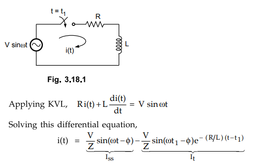
2. Analysis of RL Series Circuit
Consider
RL series circuit excited by sinusoidal voltage as shown in the Fig. 3.18.1. At
t = t1 switch is closed.
The
first term is steady state current (Iss) while the second term is
transient current (It). The waveforms are shown in the Fig. 3.18.2.
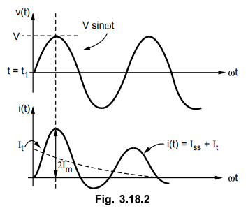
If
voltage is switched on at t = t1 when it is zero, then the transient
term has greatest value. The approximate current in this case reaches 2Im
which is known as doubling effect compared to the switching instant of
voltage when voltage is maximum.
Thus
the current flowing in the circuit changes its waveform depending on the
instant at which the voltage is applied, alternator subjected to short circuit
condition.
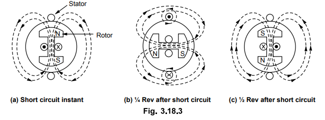
3. Short Circuit Phenomenon
Consider
a two pole elementary single phase alternator with concentrated stator winding
as shown in Fig. 3.18.3.
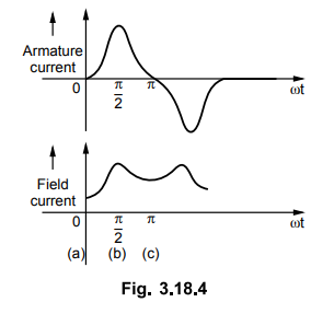
The
corresponding waveforms for stator and rotor currents are shown in the Fig.
3.18.4.
Let
short circuit occurs at position of rotor shown in Fig. 3.18.3 (a) when there
are no stator linkages. After 1/4 Rev as shown Fig. 3.18.3 (b), it tends to
establish full normal linkage in stator winding. The stator opposes this by a
current in the shown direction as to force the flux in the leakage path. The
rotor current must increase to maintain its flux constant. It reduces to normal
at position (c) where stator current is again reduces to zero. The waveform of
stator current and field current shown in the Fig. 3.18.4 changes totally if
the position of rotor at the instant of short circuit is different. Thus the
short circuit current is a function of relative position of stator and rotor.
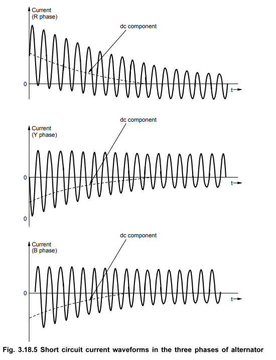
Using
the theorem of constant linkages a three phase short circuit can also be
studied. After the instant of short circuit the flux linking with the stator
will not change. A stationary image of main pole flux is produced in the
stator. Thus a d.c. component of current is carried by each phase. The
magnitude of d.c. component of current is different for each phase as the
instant on the voltage wave at which short circuit occurs is different for each
phase. The rotor tries to maintain its own poles. The rotor current is normal
each time when rotor poles occupy the position same as that during short
circuit and the current in the stator will be zero if the machine is previously
unloaded. After one half cycle from this position the stator and rotor poles
are again coincident but the poles are opposite. To maintain the flux linkages
constant, the current in rotor reaches to its peak value.
The
stationary field produced by poles on the stator induces a normal frequency emf
in the rotor. Thus the rotor current is fluctuating whose resultant a.c.
component develops fundamental frequency flux which rotates and again produces
in the stator windings double frequency or second harmonic currents. Thus the
waveform of transient current consists of fundamental, a.c. and second harmonic
components of currents.
Thus
whenever short circuit occurs in three phase generator then the stator currents
are distorted from pure sine wave and are similar to those obtained when an
alternating voltage is suddenly applied to series R-L circuit.
4. Stator Currents During Short Circuit
If
a generator having negligible resistance, excited and running on no load is
suddenly undergoing short circuit at its terminals, then the e.m.f. induced in
the stator winding is used to circulate short circuit current through it.
Initially the reactance to be taken into consideration is not the synchronous
reactance but only the leakage reactance of the machine. The effect of armature
flux (reaction) is to reduce the main field flux. But the flux linking with
stator and rotor can not change instantaneously because of the induction
associated with the windings. Thus at the short circuit instant, the armature
reaction is ineffective. It will not reduce the main flux. Thus the synchronous
reactance will not come into picture at the moment of short circuit. The only
limiting factor for short circuit current at this instant is the leakage
reactance.
After
some time from the instant of short circuit, the armature reaction slowly shows
its effect and the alternator then reaches to steady state. Thus the short
circuit current reaches to high value for some time and then settles to steady
value.
It
can be seen that during the initial instant of short circuit is dependent on
induced emf and leakage reactance which is similar to the case which we have
considered previously of voltage source suddenly applied to series R-L circuit.
The instant in the cycle at which short circuit occurs also affects the short
circuit current. Near zero e.m.f. (or voltage) it has doubling effect. The
expressions that we have derived are applicable only during initial conditions
of short circuit as the induced e.m.f. also reduces after some time because of
increased armature reaction.
The
short circuit currents in the three phases during short circuit are as shown in
the Fig. 3.18.5.
5. Single Phase Short Circuit
Consider
a single phase alternator operating under no load condition. This alternator is
suddenly short circuited. As discussed earlier during initial moment of short
circuit only leakage reactance of the machine limits the short circuit current.
Under steady state, the armature reaction produces a demagnetizing flux which
we take as synchronous reactance. Let the resistance of armature winding be
small and can be neglected.
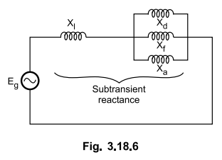
Immediately
after the short circuit, the D.C. offset currents appear in the armature
winding which can be computed separately on an emperical basis. Thus
symmetrical short circuit currents are to be considered only. Due to theorem of
constant flux linkages, the air gap flux cannot change instantaneously for
counterbalancing the demagnetizing effect of armature short circuit current,
the current is initially limited by leakage reactance only. The currents are
thus induced in the field winding and the damper winding in a direction to help
the main flux. Thus reactances Xf,Xd are in parallel with
Xa during initial period. The equivalent circuit is shown in Fig.
3.18.6. and the equivalent reactance in this case is called subtransient
reactance.
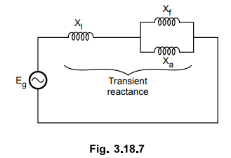
These
currents appearing in the damper winding and the field winding decay depending
upon winding time constants. The damper winding has inductance less than that
of field winding and hence current in it dies out first and afterwards Xd
is said to be effectively open circuited. The machine reactance changes from
its value of subtransient to transient consisting of parallel combination of Xf
and Xa. This is shown in the Fig. 3.18.7.
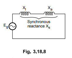
The
current in the field winding also dies out and we say that the machine is
operating in the combination of Xi and Xa. The equivalent
circuit at steady state is shown in Fig. 3.18.8.
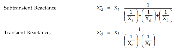
The
subtransient and transient reactances are respectively given by,
It
can be seen that X”d < X’d < X d. Thus
the machine offers variable reactance. As X”d is smallest initially
current is very large which is reduced subsequently when currents in damper
winding and field winding die out.
The
currents are given by,
I”
= Eg / X”d
I’
= Eg / X’d
I'
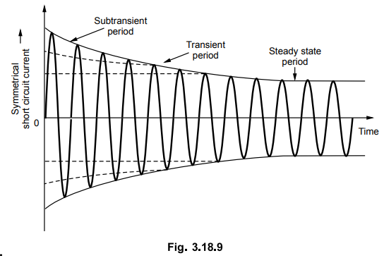
The
oscillogram of current neglecting d.c. offset currents is shown in the Fig.
3.18.9.
Review Questions
1. Discuss the short
circuit transients in three phase alternator.
2. Explain the short
circuit behaviour of single phase alternator.
Electrical Machines II: UNIT I: c. Synchronization and Parallel Operation of Alternators : Tag: Engineering Electrical Machines - II : Synchronous Generator or Alternators - Short Circuit Transients
Related Topics
Related Subjects

Electrical Machines II
EE3405 Machine 2 EM 2 4th Semester EEE Dept | 2021 Regulation | 4th Semester EEE Dept 2021 Regulation