Electric Circuit Analysis: Model Question and Answer
Solved Anna University Question Paper with Answer - 1 (PART A)
Electric Circuit Analysis
Electric Circuit Analysis: Model Question and Answer : Solved Anna University Question Paper
SOLVED ANNA
UNIVERSITY QUESTION PAPER
Question Paper Code:
40036
B.E. DEGREE
EXAMINATION, APRIL/MAY 2018
Second Semester
Electrical and
Electronics Engineering
EE 8251-CIRCUIT THEORY
(Common to Electronics and
Instrumentation Engineering and Instrumentation and Control Engineering)
(Regulation 2017)
Time: Three Hours Maximun: 100
Marks
Answer ALL questions
PART-A (10 x 2 = 20 Marks)
1. State Kirchoff's current law.
The
algebraic sum of current in a node is zero
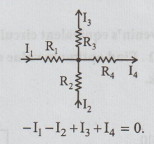
-I1
- I2 + I3+I4= 0.
2. Estimate the resultant
resistance produced by the parallel connection two resistors of 10Ω and 30 Ω.
1/R
= 1/R1 + 1/ R2
1/R
= 1/10 + 1/30
1/R
= 0.1 + 0.033
R
= 7.5 Ω
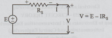
3. Draw the circuit of a pratical
voltage source and its equivalent current source.
Practical voltage source
Current source

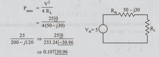
4. Let a network has Thevenin's
equivalent circuit with source of 50V and impedance of 50 j30
Ω. Find optimum value of load to derive
maximum power from the network.
Pmax
= v2/4 RL
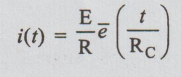
5. Define time constant and write
the time constant of a series RC circuit.
The
time constant for the RC circuit is the time during which the current falls to
36.8% of initial current.
6. Let a RL circuit has 50
Ω and 1 mH elements and free of source
but, the inductor has initial current of 1 mA at time t=0s. Find the voltage
across the resistor at time t=∞.
R
= 50 Ω, L = 1×10⁻³, io=1×10⁻³ A
Ri
+ L di/dt = 0
50i
+ 1×10⁻³ di/dt = 0
Take laplace
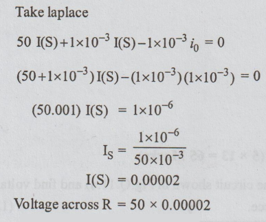
Voltage
across R = 50 × 0.00002
Voltage
across = 1 mV.
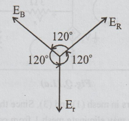
7. Draw the phasor diagram of
voltages derived from a 3-phase source.
8. In a reactive circuit, the
current leads the voltage by angle 45°. Find whether the resultant reactive is
either inductive capacitive and power factor.
9.Comment on the impedance and
phase angle between voltage and current at resonance.
If
XL = XC, the impedance is minimum and equal to resistance
at resonance the applied voltage and current are in phase.
10. If circuit resonates at 1 MHz
and produces - 3dB hand width of 100kHz
then, find the quality factor of
the circuit.
f0
= 1×10⁶
f2
- f1 = 100×103
Q
= f0 /f2 – f1
Q
= 1×10⁶ / 100×103
Q
= 10
Electric Circuit Analysis: Model Question and Answer : Tag: : Electric Circuit Analysis - Solved Anna University Question Paper with Answer - 1 (PART A)
Related Topics
Related Subjects

Electric Circuit Analysis
EE3251 2nd Semester 2021 Regulation | 2nd Semester EEE Dept 2021 Regulation