Electric Circuit Analysis: Model Question and Answer
Solved Anna University Question Paper with Answer - 1 (PART B,C)
Electric Circuit Analysis
Electric Circuit Analysis: Model Question and Answer : Solved Anna University Question Paper
PART-B (5 × 13 = 65
Marks)
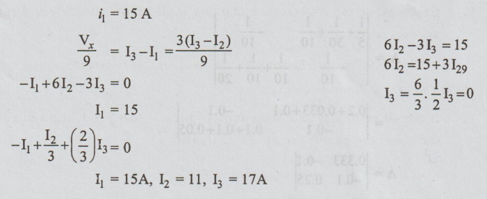
11. (a) Apply mesh analysis to the circuit shown in Fig.Q.11.a) and find voltage across the dependent source. (13)
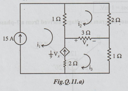
Current source appears in mesh (1) and (3). Since the 15 A source is located on perimeter of the circuit, we may eliminate mesh 1 from consideration. it is clear that i1 = 15A. The dependent current source is on the perimeter of the modified network. So we avoid any equation using for mesh 3. Only mesh 2 removes, so we apply KVL
(OR)
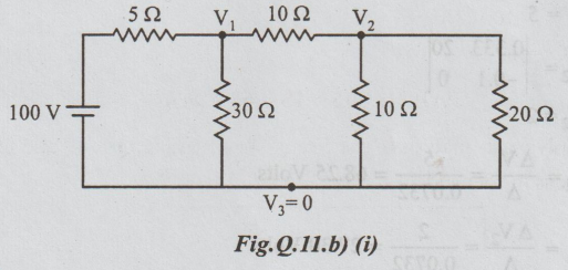
(b) Apply nodal analysis to the circuit shown in Fig.Q.11.b) (i) and fins:
(i) The voltage at each node of the circuit.(3)
Solution:
(i) Node voltage V1, V2
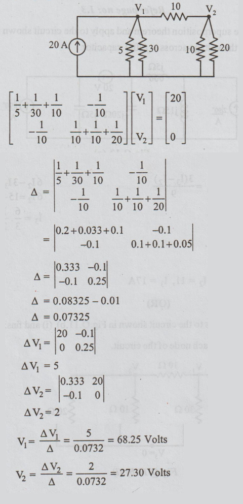
V1 = ∆ V1 / ∆ = 5/0.0732 = 68.25 Volts
V2 = ∆V2 / ∆ =2/0.0732 = 27.30 Volts
(ii)State and Explain Kirchoff's laws.(8)
Refer page no: 1.3
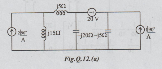
12. (a) State superposition theorem and apply to the circuit shown in Fig. 12(a) to find the voltage across -j20Ω capacitor. (13)
(i) Case  source alone
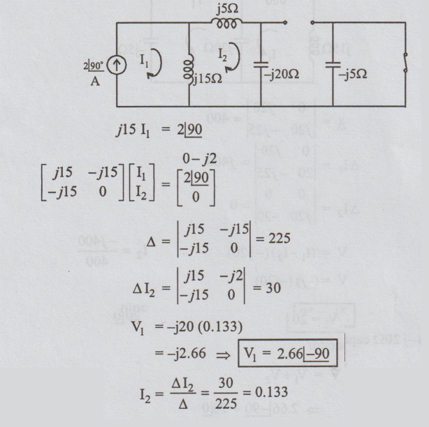
I2 = ΔΙ2 / ∆ = 30/225 = 0.133
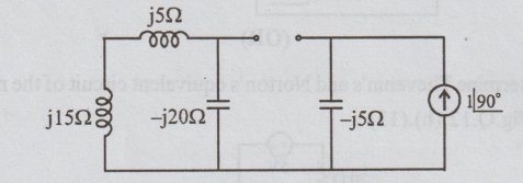
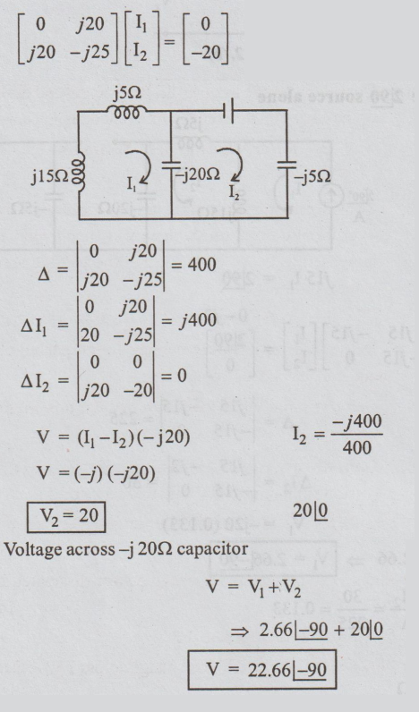
Case (ii):  Source alone
No voltage drop across the -j20 Ω because
Case (iii): 20 V alone
(OR)
(b) Determine Thevenin's and Norton's equivalent circuit of the network shown in Fig.Q.12.(b).(13)
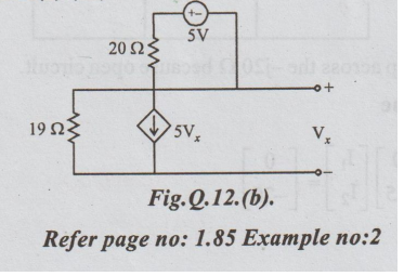
Refer page no: 1.85 Example no:2
13. (a) Consider a source free parallel RLC circuit and evaluate the voltage response of the circuit on different on different damping conditions.(13)
Refer page no: 3.21 Section no: 3.12.4
(OR)
(b) Consider a series RC circuit has been energized by a DC source of V0 Volts over infinite duration. Suddenly at time t = Os, the DC source potential increased to V1 Volts. If so, find the voltage across the capacitor for all values of time 't'. (13)
Refer page no: 3.16 Section no: 3.12.2
14. (a) Discuss the method of measuring power in a three-phase system with balanced and unbalanced load conditions. (13)
Refer page no: 4.6 Section no: 4.5 and page no: 4.16
(OR)
(b) Consider a series RLC circuit is energized by a sinusoidal signal source (assume amplitude of A, and frequency of w).
(i) What would be the instantaneous and average power delivered by source.(7)
(ii) What would be the instantaneous and average power dissipated by elements R, L and C. (6)
Refer page no: 5.1 Section no: 5.2
15. (a) Consider the circuit shown in Fig. 15.(a). find the voltage across 1 W resistor at resonance.(13)
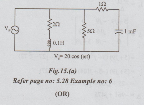
Refer page no: 5.28 Example no: 6
(OR)
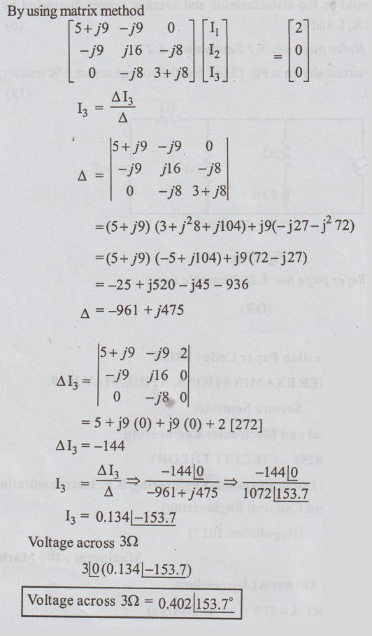
(b) Consider the circuit shown in Fig. 15.(b). Find the voltage across 3 W resistor.(13)
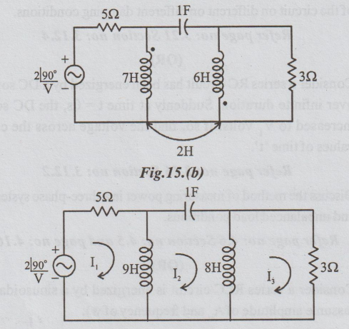
To find voltage across 3 Ω
I3 * 3Ω
By using matrix method
PART-C (1 × 15 = 15 Marks)
16. (a) Determine Thevenin's and Norton's equivalent circuits for the circuit shown in Fig. 16.(a) Also, find the optimum value of ZL to derive maximum power from the network and the resultant power derived by ZL.
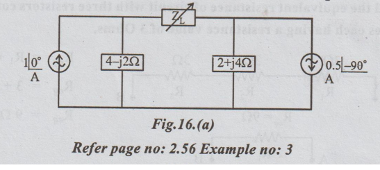
Refer page no: 2.56 Example no: 3
(OR)
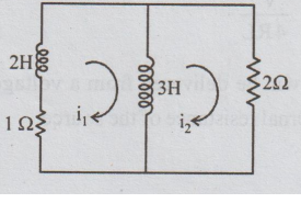
(b) For the circuit shown in Fig. 16.(b), determine expressions for i1 and i2 for t> 0, given the initial conditions, i1(0) = i2(0) = 11A.
Electric Circuit Analysis: Model Question and Answer : Tag: : Electric Circuit Analysis - Solved Anna University Question Paper with Answer - 1 (PART B,C)
Related Topics
Related Subjects

Electric Circuit Analysis
EE3251 2nd Semester 2021 Regulation | 2nd Semester EEE Dept 2021 Regulation