Electrical Machines: Unit III: a. D.C. Motors
Speed Control of D.C. Series Motor
• The flux produced by the winding depends on the m.m.f. i.e. magnetomotive force which is the product of current and the number of turns of the winding through which current is passing. So flux can be changed either by changing the current by adding a resistance or by changing the number of turns of the winding. Let us study the various methods based on this principle.
Speed Control of D.C. Series Motor
AU: May-08,
10, 11,17, 19, Dec.-06, 08, 10, 19
• The flux produced by the winding depends on the m.m.f.
i.e. magnetomotive force which is the product of current and the number of
turns of the winding through which current is passing. So flux can be changed
either by changing the current by adding a resistance or by changing the number
of turns of the winding. Let us study the various methods based on this
principle.
1. Flux Control
• The various methods of flux control in a d.c. series
motor are explained below:
a. Field Divertor
Method
• In this method the series field winding is shunted by a
variable resistance (RX) known as field divertor. The arrangement is
shown in the Fig. 4.21.1 (a).
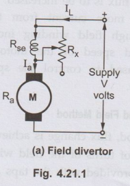
• Due to the parallel path of Rx, by adjusting
the value of Rx any amount of current can be diverted through the
divertor. Hence current through the field winding can be adjusted as per the
requirement. Due to this, the flux gets controlled and hence the speed of the
motor gets controlled.
• By this method the speed of the motor can be controlled
above rated value. The speed armature current characteristics with change in R
is shown in the Fig. 4.21.1 (b).
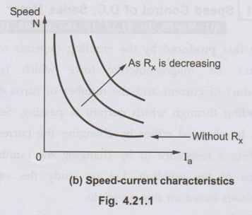
b. Armature
Divertor Method
• This method is used for the motor which require
constant load torque. An armature of the motor is shunted with an external
variable resistance (Rx) as shown in the Fig. 4.21.2. This
resistance Rx is called armature divertor
• Any amount of
armature current can be diverted through the divertor. Due to this, armature
current reduces. But as T ∞ ϕIa and load torque is constant, the
flux is to be increased. So motor reacts by drawing more current from the
supply. So current through field winding increases, so flux increases and speed
of the motor reduces. The method is used to control the speed below the normal
value.
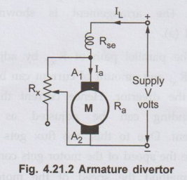
c. Tapped
Field Method
• In this method, flux change is achieved by changing the
number of turns of the field winding. The field winding is provided with the
taps as shown in the Fig. 4.21.3.
• The selector switch 'S' is provided to select the
number of turns (taps) as per the requirement. When the switch 'S' is in
position 1 the entire field winding is in the circuit and motor runs with
normal speed. As switch is moved from position 1 to 2 and onwards, the number
of turns of the field winding in the circuit decreases. Due to this m.m.f.
required to produce the flux, decreases. Due to this flux produced decreases,
increasing the speed of the motor above rated value. The method is often used
in electric traction.
d.
Series-Parallel Connection of Field
• In this method, the
field coil is divided into various parts. These parts can then be connected in
series or parallel as per the requirement. The Fig. 4.21.4 (a) and (b) show the
two parts of field coil connected in series and parallel.
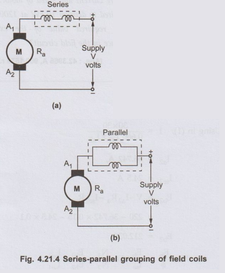
• For the same torque, if the field coil is arranged in
series or parallel, m.m.f. produced by the coils changes, hence the flux
produced also changes. Hence speed can be controlled. Some fixed speeds only
can be obtained by this method. In parallel grouping, the m.m.f. produced
decreases, hence higher speed can be obtained by parallel grouping. The method
is generally used in case of fan motors.
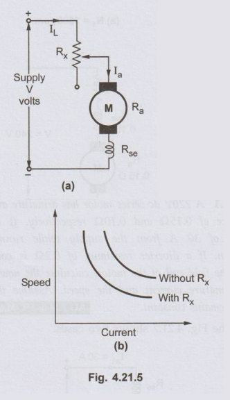
2. Rheostatic Control
• In this method, a variable resistance (Rx)
is inserted in series with the motor circuit. As this resistance is inserted,
the voltage drop across this resistance (IaRa) occurs.
This reduces the voltage across the armature. As speed is directly proportional
to the voltage across the armature, the speed reduces. The arrangement is shown
in the Fig. 4.21.5 (a). As entire current passes through Rx there is
large power loss. The speed-armature characteristics with change in Rx
are shown in the Fig. 4.21.5 (b).
3. Applied Voltage Control
• In this method, a series motor is excited by the
voltage obtained by a series generator as shown in the Fig. 4.21.6.
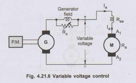
• The generator is
driven by a suitable prime mover. voltage obtained from the generator is
controlled by a field divertor resistance connected across series field winding
of the generator.
• As Eg ∝ ϕ, the flux change is achieved, gives the variable
voltage at the output terminals. Due to the change in the supply voltage, the
various speeds of the d.c. series motor can be obtained.
• Note that all the advantages and disadvantages of
various methods, discussed as applied to shunt motor are equally applicable to
speed control of series motor.
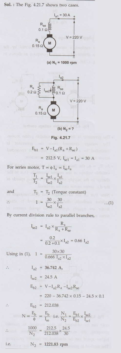
Ex. 4.21.1 A 220V dc series
motor has armature and field resistance of 0.15 Ω
and 0.10 Ω respectively. It takes a current of 30 A from the
supply while running at 1000 rpm. If a diverter resistance of 0.2 Ω is connected
across the field coil of the motor, calculate the new steady state armature
current and the speed. Assume the load torque remains constant. AU: May-19, Marks
13
Sol. :
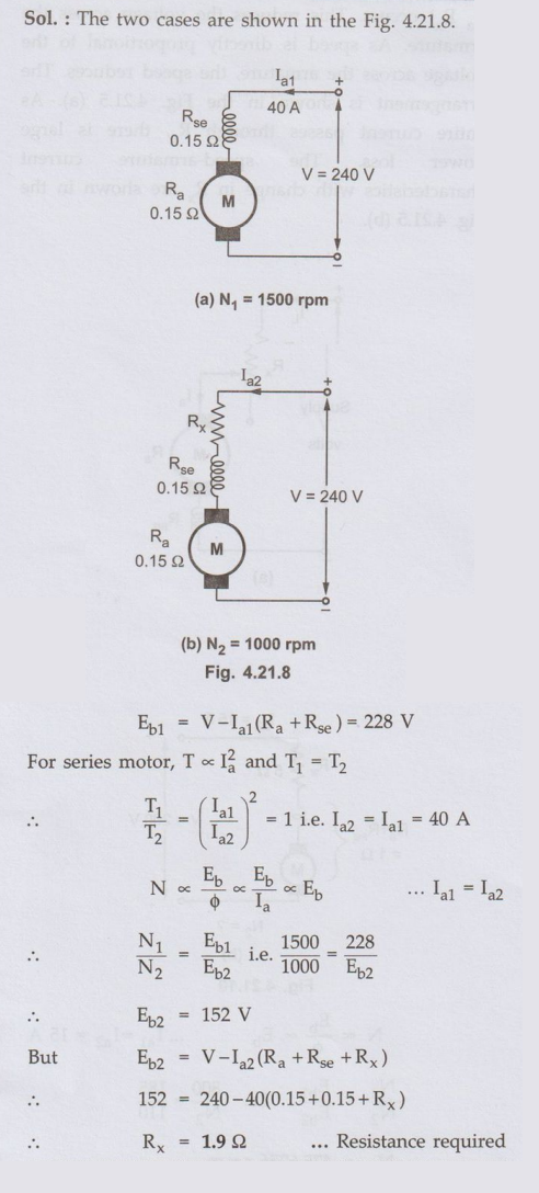
Ex. 4.21.2 A 240 V DC series
motor takes 40 A when giving its rated output at 1500 rpm. Its armature and
field resistance is 0.15 Ω and 0.15 Ω. Calculate the value of resistance which
must be added to obtain rated torque at 1000 rpm.
AU: Dec.-19,
Marks 8
Sol.
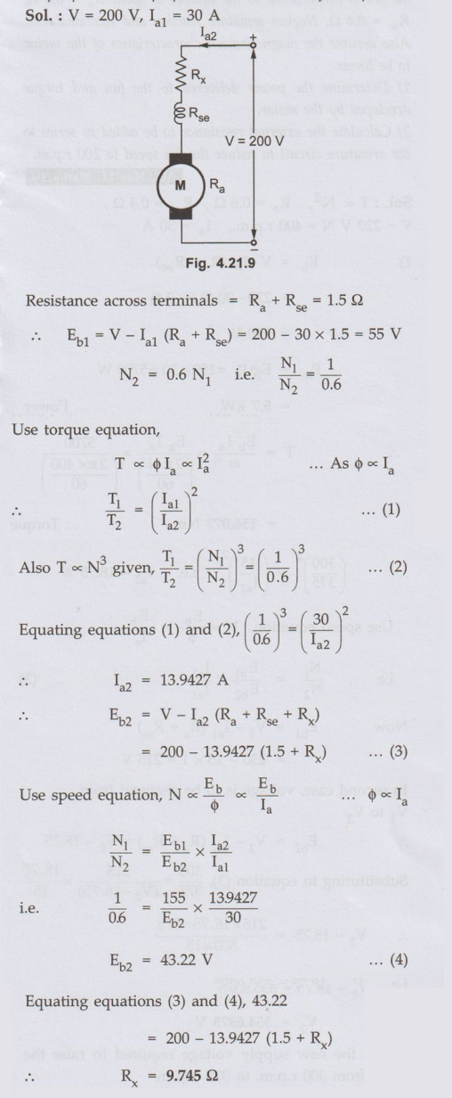
Ex. 4.21.3 A 200 V d.c.
series motor drives a load at a certain speed and takes a current of 30 A. The
resistance between its terminals is 1.5 Ω. Find the extra resistance to be
added in series with the motor circuit to reduced the speed to 60% of its
original value. Assume that the torque produced is proportional to the cube of
the speed.
Sol.:
Ex. 4.21.4 A series motor having resistance of 1 Ω between its terminals drives a fan, the torque of which is proportional to the square of the speed. At 230 V, its speed is 300 r.p.m. and takes 15 A. The speed of the fan is to be raised to 375 r.p.m. by supply voltage control. Estimate the supply voltage required.
Sol.:
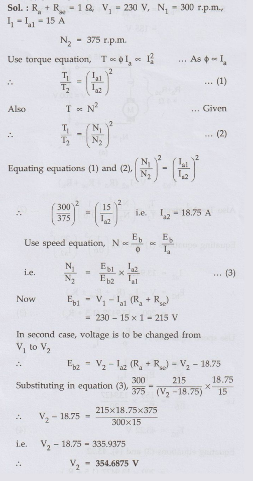
This is the new supply voltage required to raise the
speed from 300 r.p.m. to 375 r.p.m.
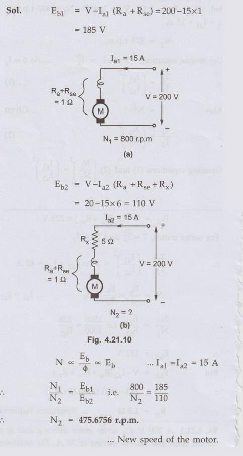
Ex. 4.21.5 A series motor of resistances 1 Ω between terminals runs
at 800 r.p.m. at 200 V with a current of 15 A. Find the speed at which it will
run when connnected in series with a 5 Ω resistance and taking the same current
at the same supply voltage.
AU: Dec.-10,
Marks 8
Sol.
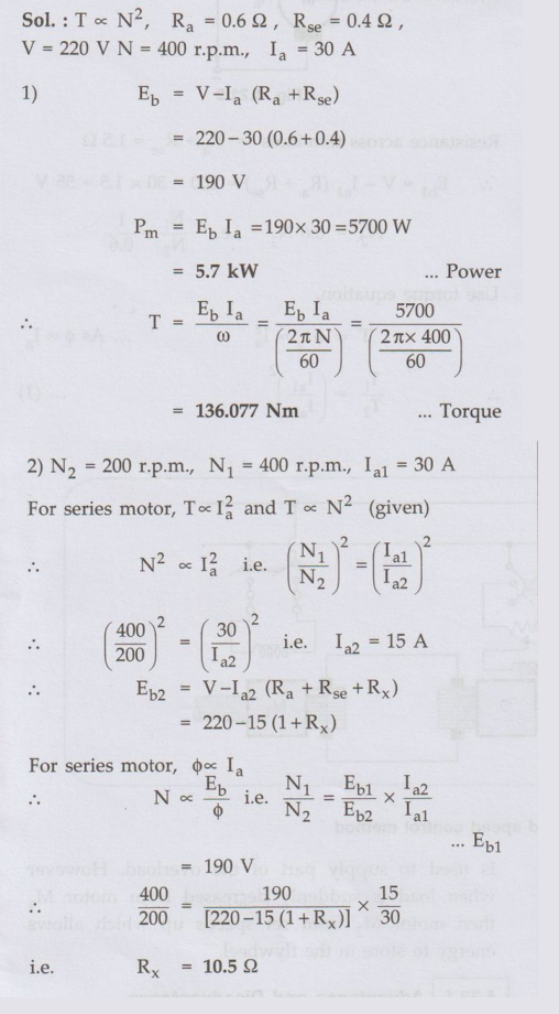
Ex. 4.21.6 A 220 V, 7.5 kW
series motor is mechanically coupled to a fan. When running at 400 r.p.m. the
motor draws 30 A from the mains (220 A). The torque required by the fan is
proportional to the squares of speed Ra= 0.6 Ω,Rse = 0.4Ω.
Neglect armature reaction and rotational loss. Also assume the magnetization
characteristics of the motor to be linear.
1) Determine
the power delivered to the fan and torque developed by the motor.
2) Calculate
the external resistance to be added in series to the armature circuit to reduce
the fan speed to 200 r.p.m. AU: May-11, Marks 10
Sol. :
Review Questions
1. Explain in detail the various methods of speed control in d.c. series
motor.
AU: Dec.-06, 08, May-08, 10, 17, Marks 8
2. A d.c. series motor runs at 500 r.p.m. on 220 V supply drawing a current of 50 A. The total resistance of the machine is 0.15 Ω, calculate the value of the extra resistance to be connected in series with the motor circuit that will reduce the speed to 300 r.p.m. The load torque being then half of the previous value. Assume flux proportional to the current.
(Ans.: 3.5225 Ω)
3. A d.c. series motor runs at 1000 r.p.m. when taking 20 A from 200 V supply. Its armature resistance is 0.5 Ω and series field resistance is no 0.2 Ω. Find the speed if continues to draw a current of 20 A but a field winding is shunted with a resistance of 0.2 Ω. Assume that flux for the field winding when carrying 10 A is 70 % of that when carrying 20 A.
(Ans. : 1443.93 r.p.m.)
4. A 200 V d.c. series motor drives a load at a certain speed and takes a current of 30 A. The resistance between its terminals is 1.5 ohms. Find the value of the extra resistance to be added in series with the armature to reduce the soppd to 60% of its original value. Assume torque is proportional to cube of speed.
(Ans.: 9.745 Ω)
5. A d.c. series motor runs at 1000 r.p.m. when taking current of 10 A at 200 volts, with both field coils in series. Its armature resistance is 0.01 ohm and resistance of each field coil is 0.02 ohm. Calculate the speed of the motor, if the field coils were connected in parallel with each other, the load torque being constant. Assume magnetic field to be unsaturated.
(Ans. 1415.76 r.p.m.)
6 A 220 volts d.c. series motor runs at 800 r.p.m. when taking a current of 15 amperes. The motor has an armature resistance of 0.3 ohm and series field resistance of 0.2 ohm. Find the resistance to be connected in series with the armature if it has to take the same current at same voltage at 600 r.p.m.
(Ans.: 3.5416Ω)
7. A 4 pole d.c. series motor has 820 wave connected armature conductors. The flux per pole is 35 mWb and the torque developed is 200 N-m. Calculate the current taken by the motor and the speed at which it will run with an applied voltage of 500 V. Armature resistance is 1.5 Ω and the series RU ORIA field resistance is 1.0 Ω.
(Ans.: 21.8926 A, 488.3217 r.p.m.)
Electrical Machines: Unit III: a. D.C. Motors : Tag: : - Speed Control of D.C. Series Motor
Related Topics
Related Subjects

Electrical Machines I
EE3303 EM 1 3rd Semester EEE Dept | 2021 Regulation | 3rd Semester EEE Dept 2021 Regulation