Electrical Machines: Unit III: a. D.C. Motors
Speed Control of D.C. Shunt Motor
• Out of the three methods, let us study flux control method.
Speed
Control of D.C. Shunt Motor
AU: Nov.-04, Oct.-98, April-97,
Dec.-05,06,07,08,14,17,18
May-05,06,07,08,10,11,12,13,14,17,19
• Out of the three
methods, let us study flux control method.
1. Flux Control
•
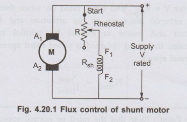
As indicated by the speed equation, the speed is inversely proportional to the
flux. The flux is dependent on the current through the shunt field winding.
Thus flux can be controlled by adding a rheostat (variable resistance) in
series with the shunt field winding, as shown in the Fig. 4.20.1.
• At the beginning the
rheostat R is kept at minimum indicated as start in the Fig. 4.20.1. The supply
voltage is at its rated value. So current through shunt field winding is also
at its rated value. Hence the speed is also rated speed also called normal
speed. Then the resistance R is increased due to which shunt field current Ish
decreases, decreasing the flux produced. As N ∝ 1 / ϕ), the speed of the motor increases
beyond its rated value.
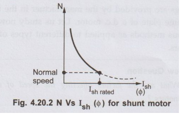
• Thus by this method,
the speed control above rated value is possible. This is shown in the Fig.
4.20.2, by speed against field current curve. The curve shows the inverse
relation between N and o as its nature is rectangular hyperbola.
• It is mentioned that
the rated values of electrical parameters should not be exceeded but the speed
which is mechanical parameter can be increased upto twice its rated value.
a. Advantages of Flux Control
Method
1.
It provides relatively smooth and easy control.
2.
Speed control above rated speed is possible.
3.
As the field winding resistance is high, the field current is small. Hence
power loss (I2sh R) in the external resistance is very
small, which makes the method more economical and efficient.
4.
As the field current is small, the size of the rheostat required is small.
b. Disadvantages of Flux Control
Method
1.
The speed control below normal rated speed is not possible as flux can be
increased only upto its rated value.
2.
As flux reduces, speed increases. But high speed affects the commutation making
motor operation unstable. So there is limit to the maximum speed above normal,
possible by this method.
2. Armature Voltage Control Method or Rheostatic Control
• The speed is directly
proportional to the voltage applied across the armature. As the supply voltage
is normally constant, the voltage across the armature can be controlled by
adding a variable resistance in series with the armature as shown in the Fig.
4.20.3.
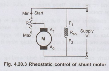
• The field winding is
excited by the normal voltage hence Ish is rated and constant in this method.
Initially the rheostat position is minimum and rated voltage gets applied
across the armature. So speed is also rated. For a given load, armature current
is fixed. So when extra resistance is added in the armature circuit, Ia
remains same and there is voltage drop across the resistance added (IaRa).
Hence voltage across the armature decreases, decreasing the speed below normal
value. By varying this extra resistance, various speeds below rated value can
be obtained.
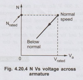
• So for a constant load
torque, the speed is directly proportional to the voltage across the armature.
The relationship between speed and voltage across the armature is shown in the
Fig. 4.20.4.
a. Potential Divider Control
• The main disadvantage
of the above method is, the speed upto zero is not possible as it requires a
large rheostat in series with the armature which ispractically impossible. If
speed control from zero to the rated speed is required, by rheostatic method
then voltage across the armature can be varied by connecting rheostat in a
potential divider arrangement as shown in the Fig. 4.20.5.
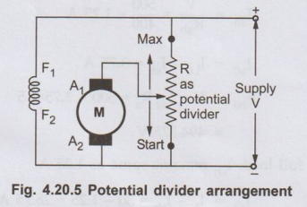
• When the variable
rheostat position is at 'start' point shown, voltage across the armature is
zero and hence speed is zero. As rheostat is moved towards 'maximum' point
shown, the voltage across the armature increases, increasing the speed. At
maximum point the voltage is maximum i.e. rated hence maximum speed possible is
rated speed. The relationship is shown in the Fig. 4.20.6.
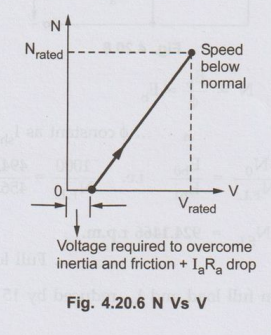
• When the voltage across the armature starts
increasing, as long as motor does not overcome inertial and frictional torque,
the speed of the motor remains zero. The motor requires some voltage to start
hence the graph of voltage and the speed does not pass through the origin as
shown in the Fig. 4.20.6.
b. Advantages of Rheostatic Control
1.
Easy and smooth speed control below normal is possible.
2.
In potential divider arrangement, rheostat can be used as a starter.
c. Disadvantages of Rheostatic
Control
1.
As the entire armature current passes through the external resistance, there
are tremendous power losses.
2.
As armature current is more than field current, rheostat required is of large
size and capacity.
3.
Speed above rated is not possible by this method.
4.
Due to large power losses, the method is expensive, wasteful and less
efficient.
5.
The method needs expensive heat dissipation arrangements.
3. Applied Voltage Control
• Multiple
voltage control: In this technique the shunt field of the
motor is permanently connected to a fixed voltage supply, while the armature is
supplied with various voltages by means of suitable switch gear arrangements.
• The Fig. 4.20.7 shows a control of motor by two different working voltages which can be applied to it with the help of switch gear.
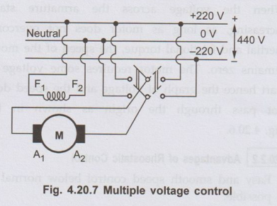
• In large factories,
various values of armature voltages and corresponding arrangement can be used
to obtain the speed control.
a. Advantages of Applied Voltage
Control
1.
Gives wide range of speed control.
2.
Speed control in both directions can be achieved very easily.
3.
Uniform acceleration can be obtained.
2. Disadvantages of Applied Voltage
Control
1.
Arrangement is expensive as provision of various auxiliary equipments is
necessary.
2.
Overall efficiency is low.
* General steps to solve problems
on speed control
1. Identify the method of speed control i.e.
in which winding of the motor, the external resistance is to be inserted.
2.Use
the torque equation, T ∝
ϕ Ia to determine the new armature current according to the
condition of the torque given. Load condition indicates the condition of the
torque.
3.
Use the speed equation N ∞ Eb /
Φ to find the unknown back e.m.f. or field current.
4.
From the term calculated above and using voltage current relationship of the
motor, the value of extra resistance to be added, can be determined. The above
steps may vary little bit according to the nature of the problem but are always
the base of any speed control problem.
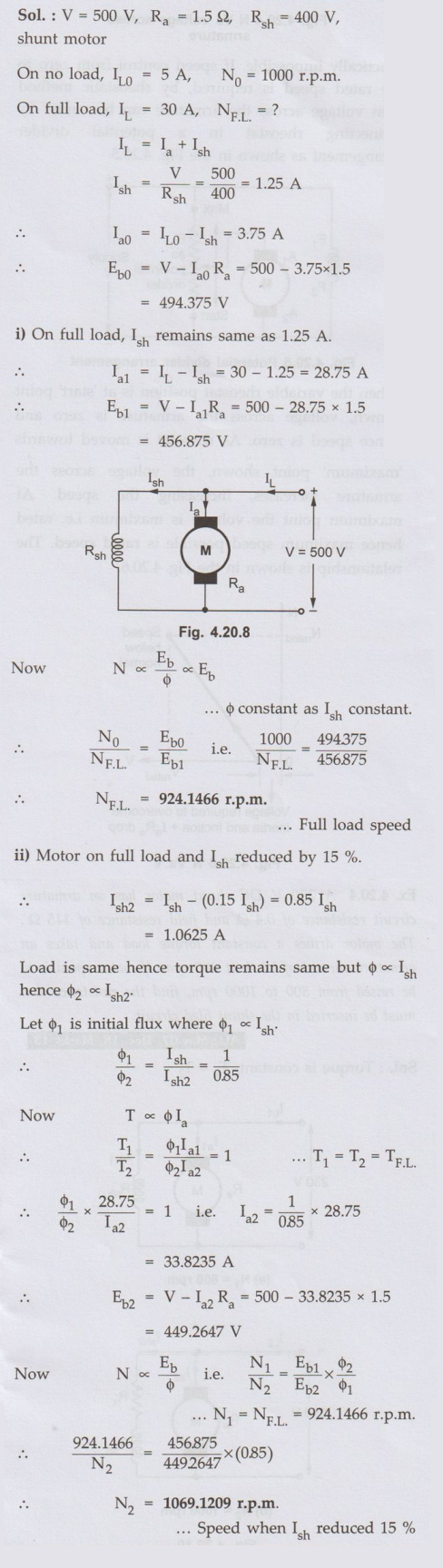
Ex. 4.20.1
A 500 V d.c. shunt motor has armature and
field resistances of 1.5 Ω and 400 Ω respectively. When running on no load the
current taken is 5 Amps and the speed is 1000 r.p.m. Calculate the speed when
motor is fully loaded and the total current drawn from the supply is 30 Amps.
Also estimate the speed at this load if the shunt field current is reduced by
15 %.
AU: Nov.-04, Marks 8
Sol.
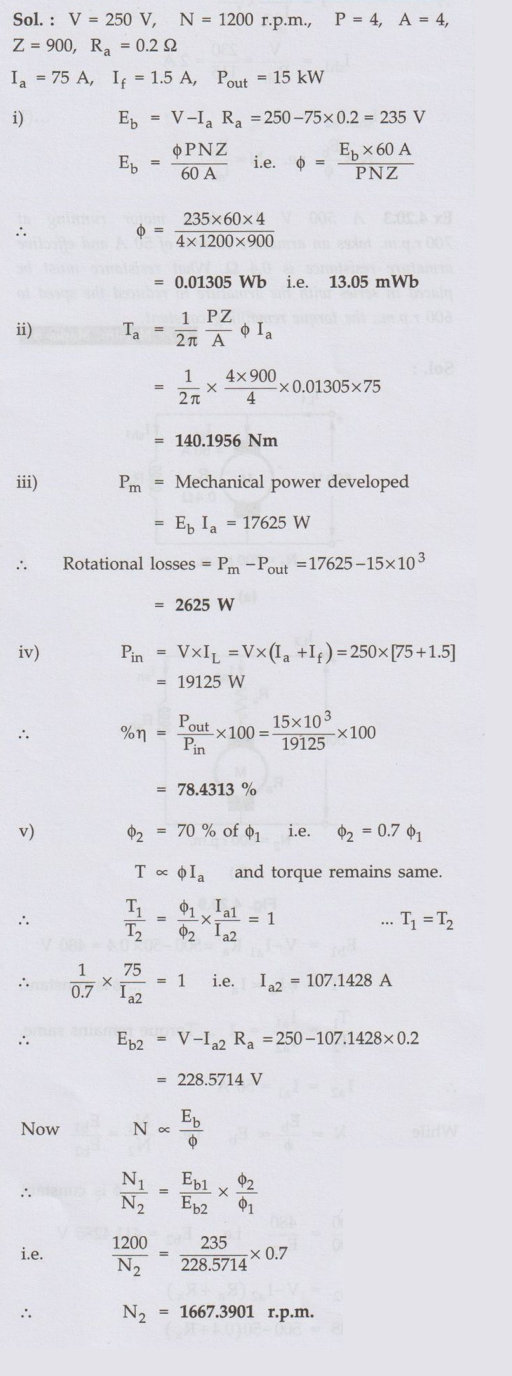
Ex. 4.20.2
A 15 kW, 250 V, 1200 r.p.m. shunt motor
has 4 poles, 4 parallel armature paths and 900 armature conductors. Assume Ra
= 0.2 •Ω. At rated speed and rated output the armature current is 75 A and If
= 1.5 A Calculate i) The flux/pole ii) The torque developed iii) Rotational
losses iv) Efficiency v) The shaft load vi) If the shaft load remains fixed,
but the field flux is reduced to 70% of its value by field control, determine
the new operating speed.
AU: Dec.-05, Marks 10
Sol. :
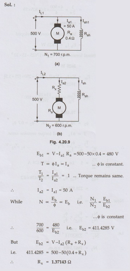
Ex 4.20.3
A 500 V d.c. shunt motor running at 700
r.p.m. takes an armature current of 50 A and effective armature resistance is
0.4 Ω. What resistance must be placed in series with the armature to reduced
the speed to 600 r.p.m., the torque remaining constant.
AU: May-06, Marks 8
Sol. :
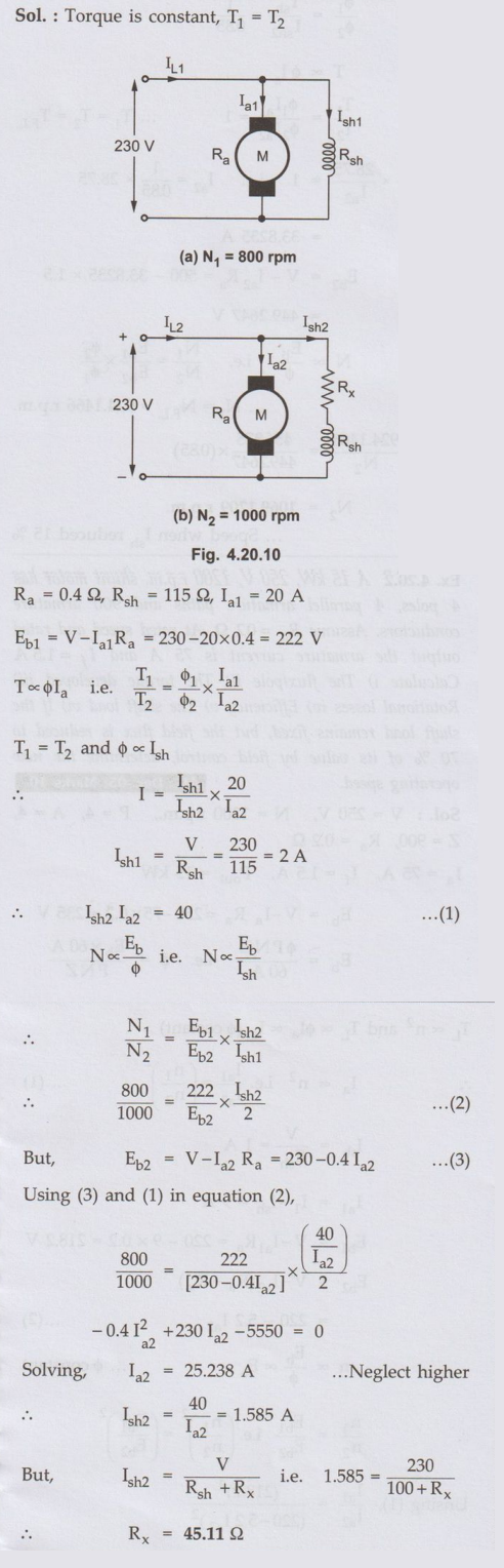
Ex. 4.20.4
A 230 V DC shunt motor has an armature
circuit resistance of 0.4 Ω and field resistance of 115 Ω. The motor drives a
constant torque load and takes an armature current of 20 A at 800 rpm. If motor
speed is to be raised from 800 to 1000 rpm, find the resistance that must be
inserted in the shunt filed circuit.
AU: May-07, Dec.-18, Marks 13
Sol. :
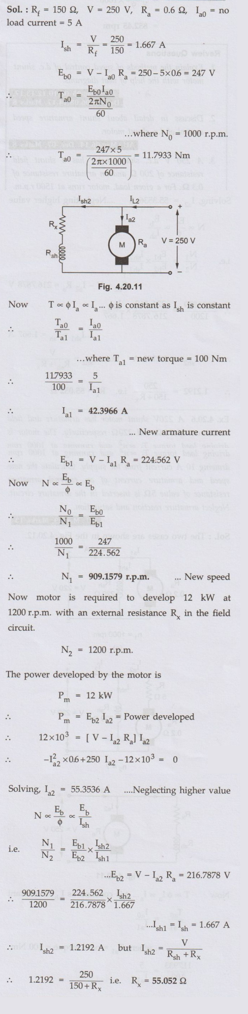
Ex. 4.20.5 A 250-V dc shunt motor
has Rf = 150 Ω and Ra = 0.6 Ω. The motor operates on
no-load with a full field flux at its base speed of 1000 r.p.m. with Ia =
5 A. If the machine drives a load requiring a torque of 100 Nm, calculate
armature current and speed of motor. If the motor is requird to develope 12 kW
at 1200 r.p.m. what is the required value of the external series resistance in
the field circuit? Assume linear magnetization. Neglect saturation and armature
reaction. AU:
Dec.-07, May-11, Marks 16
Sol.:
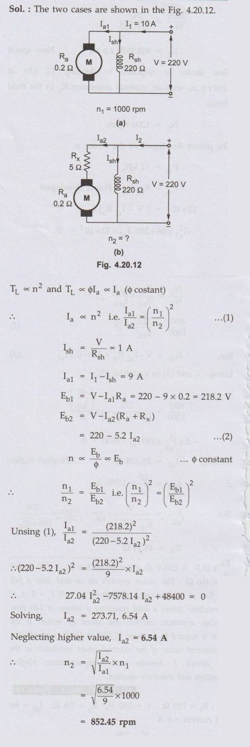
Ex. 4.20.6 A 220V shunt motor
has armature and field resistances of 0.2 Ω
and 220Ω respectively. The motor is driving load torque TL ∝n2 and running at 1000 rpm drawing 10 A
current from the supply. Calculate the new speed and armature current of an
external armature resistance of value 52 is inserted in the armature circuit. Neglect
armature reaction and saturation.
AU:May-19,
Mark 13
Sol. :
Review Questions
1. Explain the methods of speed control of d.c. shunt motor with the help
of neat diagrams.
AU: May-05 08,10,12,13,17, Dec.-05,06,08,14,17, Marks 8
2. Discuss in detail about shunt armature speed control of d.c. shunt
motor.
AU: May-06,14, Dec.-07, Marks 8
3. A 250 V d.c. shunt motor has a shunt field resistance of 200 Ω and an
armature resistance of 0.3Ω. For a given load, motor runs at 1500 r.p.m. drawing
a current of 22 A from the supply. If a resistance of 150 Ω is added in series
with the field winding, find the new armature current and the speed. Assume
load torque constant and magnetization curve to be linear.
(Ans.: 36.3125 A, 2575.03 r.p.m.)
4. A 250 V, 10 h.p., d.c. shunt motor with Ra = 0.4 Ω and Rsh = 100 Ω, runs at 1000 r.p.m. on full load. Efficiency on full load is 85 %. If speed is to be raised to 1400 r.p.m. keeping load constant, determine extra resistance to be added in the field circuit. Assume 1 h.p = 735.5 watts.
(Ans. : 43.362)
5. A 220 V d.c. shunt motor has an
armature resistance of 0.5 Ω and is excited to produce constant flux. At full load the motor runs at
no1000 r.p.m. taking an armature current of 40 A. If a resistance of 0.8 Ω is
inserted in series with the armature, determine speed at the full load.
AU: April-97 (Ans.: 840 r.p.m.)
6. A 230 V d.c. shunt motor runs at 1000 r.p.m. on full load, drawing a
current of 10 A. The shunt field resistance is 230 Ω and the armature
resistance is 0.5 Ω. Calculate the resistance to be inserted in series with the
armature so that the speed at full load is 950 r.p.m. AU: Oct.-98
(Ans.: : 1.25282)
7. A 250 V d.c. shunt motor has Rf = 150 Ω Ra = 0.6 9. The motor operates
on no load r.p.m. with a full field flux at its base speed of 1000 r.p.m. with
Ia= 5 A. If the machine drives a load requiring a torque of 100 Nm,
calculate armature current and speed of motor. If the motor is required to
develop 10 kW at 1200 r.p.m., what is the required value of the external series
resistance in the field circuit?
AU: Dec.-07
(Ans.: 42.3966 A, 909.1579 r.p.m.,55.052 Ω)
Electrical Machines: Unit III: a. D.C. Motors : Tag: : - Speed Control of D.C. Shunt Motor
Related Topics
Related Subjects

Electrical Machines I
EE3303 EM 1 3rd Semester EEE Dept | 2021 Regulation | 3rd Semester EEE Dept 2021 Regulation