Digital Logic Circuits: Unit V: VHDL
Structure of Behavioral Description
VHDL
• An entity declaration describes the external interface of the entity. It specifies the name of the entity, the names of input/output ports, and the type of ports. The syntax for an entity declaration is as shown below.
Structure of Behavioral Description
AU
: Dec.-l0, 18, May-16, 17
1. Entity Declaration
•
An entity declaration describes the external interface of the entity. It
specifies the name of the entity, the names of input/output ports, and the type
of ports. The syntax for an entity declaration is as shown below.
entity
entity_name is
generic
(list of generics and their types);
Port
(list of port names and their types
entity
item declarations
begin
entity
statements
end
entity_name;
The
port in the behavioral modeling can have one of the following modes :
in
:
This mode is used for a signal that is an input to an entity (value is read not
written).
out:
It is used for a signal that is an output from an entity. The value of such a
signal can not be read inside the entity's architecture. But it can be read by
other entities those use it.
inout: It is used for a
signal that is both, an input to an entity and an output from the entity.
buffer
:
The signal is an output from the entity and its value can also be read inside
the architecture of entity. The buffer is different from inout mode in that it
cannot have more than one source.
Linkage
:
The value of a linkage port can be read and updated. This can be done only by
another port of mode linkage.
•
The entity item declaration includes those declarations that are common to all
the design unit. The Fig. 10.7.1 shows the circuit for half-adder and its
entity declaration is

entity
half_adder is
port
( A : in bit;
B
: in bit;
Sum
: out bit;
Cout
: out bit);
end
half_adder;
2. Architecture Body
•
Architecture specifies behavior, functionality, interconnections or
relationship between inputs and outputs. It is the actual description of the
design.
•
The syntax of an architecture body is :
architecture
architecture_name of entity_name is
architecture
item declarations
begin
Concurrent
statements ; these include ->
process
statement block statement
concurrent
procedure call
statement
concurrent
assertion statement
concurrent
signal assignment
statement
component
instantiation statement generate statement
end
architecture_name;
•
All concurrent statements execute in parallel and therefore their sequence in
the architecture body does not matter the behavior of the circuit. The
architecture body for half_adder is :
architecture
adder of half_adder is
begin
process
(A, B)
begin
Sum
< = A xor B ;
Cout
< = A and B ;
end
process;
end
adder;
3. Variable Assignment Statement
•
We can use variables inside the processes. This is illustrated by the following
statements :
process
(X)
variable
A, B : bit; - variable
declaration statement
begin
st
l : A : =X; - Variable assignment
statement
st2
: B := not A; - Variable assignment statement
st3
: O1 < = A; - use < = assignment operator
end
process ;
•
Variable assignment statements, as in C language, are calculated and assigned
immediately with no delay time between calculation and assignment. The
assignment operator : = is used assigned values to the variables instead of
assignment operator <=.
•
One important thing to note that we can label any statement in the VHDL such as
stl, st2 and st3 in the previous description.
4. Sequential Statements
•
The various forms of sequential statements are associated with behavioral
description. These statements have to appear inside process in VHDL. These
statements execute in the order in which they appear. Let us study these
sequential statements.
a.
IF Statement
•
An IF statement selects a sequence of statements for execution based on the
value of a condition. The condition can be any expression that evaluates to a
Boolean value.
VHDL
Syntax :
if
(Boolean Expression) then
statement
1;
statement
2;
.
.
.
else
statement
x;
statement
y;
end
if;
Example
:
if
(EN = '1') then
Q
:= S1;
else
Q:
= S2;
end
if;
In
the above examples, if EN = T' (high), then the value of SI is assigned to Q;
otherwise, the value of S2 is assigned to Q.
Ex.
10.7.1 : Execution of IF as a D latch.
if
Clk = '1'
then
Q:= D;
end
if;
if
Clk is T (high), then the value of D is assigned to output Q. If Clk is not
high, Q retains its current value, thus simulating a latch.
Ex.
10.7.2 : Execution of IF as ELSE-IF
VHDL
syntax :
If
(Boolean Expression 1) then
statement
1 ; statement 2; ...
elsif
(Boolean Expression 2) then
statement
x; statement y; ...
else
statement
a; statement b; ...
end
if ;
Example
:
process
(a, b, en)
begin
if
en = '00' then
c
< = a;
elsif
en = '01' then
c
< = b;
else
c
< = '0';
end
if;
end
process;
Here
'en' signal is in sensitivity list. If en = 00, signal 'a' is assigned to
output 'c'. Similarly if 'en' = '01' then 'b' is assigned to 'c' else 'O' value
is assigned to 'c'.
Ex.
10.7.3 : Behavioral description of 2 × 1 multiplexer using IF ELSE
VHDL
2 x 1 Multiplexer Using IF-ELSE
library
ieee;
use
ieee.std_logic_1164.all;
entity
mux2 × 1 is
port
( DO, DI, S, Enbar : in std_logic;
Y
: out std_logic);
end
mux2 × 1;
architecture
MUX of mux2 × 1 is
begin
process
(S, DO, DI, Enbar)
-
S, DO, DI and Enbar are the sensitivity
list
of the process.
variable
temp : std_logic;
-
It is common practice in behavioral description to use variable(s) rather than
signal(s). This is done to avoid any timing errors that may arise due to the
sequential execution of signal statements.
begin
if
Enbar = '0' then
if
S = '1' then
temp
:= D1;
else
temp
:= D0;
end
if;
Y
< = temp;
else
Y
< = 'Z';
end
if;
end
process;
end
MUX;
Ex.
10.7.4 : Behavioral description of a 2 × 1 multiplexer using ELSE IF.
VHDL
2 × 1 Multiplexer Using ELSE-IF
library
ieee;
use
ieee.std_logic_1164.all;
entity
mux2 × 1 is
port
(DO, DI, S, Enbar : in std_logic;
Y
: out std_logic);
end
mux2×l;
architecture
MUX of mux2×l is
begin
process
(S, DO, DI, Enbar)
-
S, DO, DI and Enbar are the sensitivity
list
of the process.
variable
temp : std_logic;
begin
if
Enbar = 'O' and (S = '1') then
temp
:= D1;
elsif
Enbar = '0' and (S = 'O') then
temp
:= D0;
else
temp
:= 'Z'; - 'Z' represents high impedance
state
end
if;
Y
< = temp;
end
process;
end
MUX;
b.
Signal and Variable Assignment
•
There is a difference between the execution of signal assignment statement and
variable assignment statement. We know that signal assignment statement
executes in two phases : calculation and assignment. For signal, actual
assignment of new value is delayed by the propagation delay. On the other hand,
when we use variable assignment statements, variables acquire their new values
instantaneously. Due to this difference in two assignments, simulation result
may be different if we use signals instead of variables. This is illustrated in
the example 10.7.5.
Ex.
10.7.5 : Behavioral description of a latch using variable and signal
assignment.
•
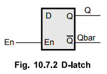
The Fig. 10.7.2 shows the logic symbol for D latch. It has input (D), output Q
and Qbar and active high enables input (En). When En is high, the output Q
follows input D and Qbar is always the invert of Q.
Listing
10.7.1 : VHDL code for behavioral description of D-Latch
using variable - assignment statements
entity
DLatch_var is
port
(D, En : in bit;
Q,
Qbar : out bit);
end
DLatch_var;
architecture
DL_Var of DLatch_var is
begin
VAR
: process (D, En)
variable
tempi, temp2 : bit;
begin
if
En = '1' then
temp1
:= D; - Variable assignment statement.
temp2
:= not temp1; - Variable assignment statement
end
if;
Q
< = tempi; - Value of temp 1 is assignd to Q
Qbar
<= temp2; - Value of temp 1 is assignd to Qbar
end
process VAR;
end
DL_Var;
Listing
10.7.2 : VHDL code for behavioral description of D-Latch
using signal-assignment statements
entity
DLatchsig is
port
(D, En : in bit;
Q
: buffer bit;
Qbar
: out bit);
-
Q is declared as a buffer because it is an input/output signal.
-
it appears on both the left and right hand sides of assignment statements.
end
DLatch_sig;
architecture
DL_sig of DLatch_sig is
begin
process
(D, En)
begin
if
En = '1' then
Q
< = D; - signal assignment
Qbar
< = not Q; - signal assignment
end
if;
end
process;
end
DL_sig;
The
Table 10.7.1 gives the comparison between signal and variable.

•
The Fig. 10.7.2 shows the simulation waveform of D latch using variable
assignment statement. This waveform correctly describes D-latch. The Fig.
10.7.4 shows the simulation waveform of D latch using signal assignment
statement. As shown in the Fig. 10.7.4, at T = 50 ns, En changes from 0 to 1,
and D is 1 at T = 50 ns. Therefore, new value for Q is calculated as 1;
however, it is assigned at T = 50 + A Since at T = 50 ns, value of Q is still
0, Qbar is calculated as 1 using old value of Q.

c.
Case Statement
•
The case statement is a special multi-way decision statement that tests whether
an expression matches one of a number of other expressions, and branches
accordingly. It has following syntax :
VHDL
case
(control-expression) is
when
test value or expression 1 ⇒
statements 1;
when
test value or expression 2 ⇒
statements 2;
⁞
when
others ⇒ statements n;
end
case;
•
The expression value may be expressed as single value, or as a range of values
or as a value of specified expression. The statement when others can be used to
guarantee that all conditions are covered. Use of multiple when others
statements in one case statement is illegal.
Example
:
VHDL
case
option is
when
"00" ⇒ temp
:= a + b;
when
"01" ⇒ temp
:= a - b;
when
"10" ⇒
temp := a* b;
when
others ⇒ temp : = a / b;
end
case;
•
In above example, the control is option. If option = 00, then temp = a + b; if
option = 01, then temp = a - b; if option = 10, then temp = a * b; if option =
11 (others or default), then temp = a / b;
d.
Comparison between CASE and IF Statement
•
IF statement produces priority encoded logic.
Example
:
process
(sel, a, b, c, d)
begin
if
sel = '00' then
op
< = a;
elsif
sel ='01' then
op
< = b;
elsif
sel ='10' then
op
< = c;
else
op
< = d;
end
if;
end
process;
•
Here, priority encoded logic means firstly the IF statement executes
sequentially, so depending on the first IF condition that particular input is
connected to output. Next depending on the second IF condition, the another
input is passed to output. According to this logic, for this example, three
multiplexer are generated by tool. So in this case hardware is more so the
delay generated by logic gates is more; so the speed is reduced.
•
The case statement produces parallel logic. Here, in case statement depending
on the value of "sel" one of the four inputs is passed to the output.
So a single multiplexer of 4 inputs with two select lines and one output is
generated by a tool. So the generated hardware is less, so the delay by logic
gates is less; so the speed is high.
Example
:
process
(sel, a, b, c, d)
begin
case
sel is
when
'00' = >op < = a;
when
'01' = >op < = b;
when
'10' = >op <= c;
when
others = >op < = d;
end
case;
end
process;
Ex.
10.7.6 : Behavioral description of a positive edge triggered JK flip-flop using
the case statement.
The
Fig. 10.7.5 (a) shows the clocked JK flip-flop, logic symbol and truth table
for clocked edge triggered or pulse triggered JK flip-flop.
We
know that, in case of pulse or edge triggering the flip-flop changes state
either at the positive edge (rising edge) or at the negative edge (falling
edge) of the clock pulse and is sensitive to its inputs only at this transition
of the clock. Fig. 10.7.6 shows the input and output waveforms for positive
edge triggering JK flip-flop.


Looking
at the truth table for JK flip-flop and simplifying Qn +1 function by K-map we
get the characteristic equation for JK flip-flop as

Listing
10.7.3 : HDL code for a positive edge-triggered JK flip-flop
using the case statement-VHDL.
VHDL
Positive Edge-Triggered JK Flip-Flop Using Case
library
ieee;
use
ieee.std_logic_1164.all;
entity
JK_FF is
port(
JK : in bit_vector (1 downto 0);
clk
: in std_logic;
Q,
Qbar : out bit);
end
JK_FF;
architecture
Flip_Flop of JK_FF is
begin
P1
: process (elk)
variable
tempi, temp2 : bit;
begin
if
rising_edge (elk) then
case
JK is
when
"01" => tempi := '0';
when
"10" => tempi := '1';
when
"00" => tempi := temp1;
when
"11" => tempi := not temp1;
end
case;
Q
< = temp1;
temp2
:= not tempi;
Qbar
< = temp2;
end
if;
end
process P1;
end
Flip_Flop;
Ex.
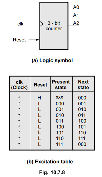
10.7.7 : Behavioral description of a 3-bit up counter.
A
counter is a register capable of arriving at its clock input. For up counters,
the next state is the increment of the present state. For example, if the
present state is 010, then the next state is Oil. For down counters, the next
state is the decrement of the present state. A 3-bit up counter counts from 0
to 7, i.e., it is a mod 8 counter.
The
Fig. 10.7.8 shows the logic symbol and excitation table for 3-bit counter. It
has two inputs : elk and Reset (active high). On the positive edge of the elk
(Clock) input counter increments only if Reset input is 0 (Low); otherwise
counter output is reset to 000.
Listing
10.7.4 : HDL code for a 3-bit binary counter using the case
statement.
VHDL
3-Bit Binary Counter Case Statement Description
library
ieee;
use
ieee.std_logic_1164.all;
entity
CTCase is
port
( elk, Reset : in std_logic;
Q
: buffer std_logic_vector (2 downto 0));
end
CT_Case;
architecture
Counter_3b of CT_case is
begin
counter
: process(clk)
variable
temp : std_logic_vector (2 downto 0) := "011";
-
011 is the initial value, so the
counter
starts from 100
begin
if
rising_edge (elk) then
if
Reset = '0' then
case
temp is
when
"000" => temp := "001";
when
"001" => temp := "010";
when
"010" => temp := "011";
when
"Oil" => temp := "100";
when
"100" => temp := "101";
when
"101" => temp := "110";
when
"110" => temp := "111";
when
"111" => temp := "000";
when
others => temp := "000";
end
case;
else
temp
:= "000";
end
if;
end
if;
Q
< = temp;
end
process counter;
end
counter_3b;
Ex.
10.7.8 : Construct a VHDL module listing for a 16 : 1 MUX that is based on the
assignment statement. Use a 4-bit select word S3, S2, S1
, S0 to map the selected input Pi (i = 0, 15) to the
output
AU
: Dec.-10, Marks 16
Solution
:
library
IEEE;
use
IEEE.STD_LOGIC_1164.ALL;
entity
Mux8_1 is
port
( SEL: in STD_LOGIC_VECTOR(3 downto 0);
P0,
Pl, P2, P3, P4, P5, P6, P7, P8, P9, P10 , PH, P12,
P13,
P14, P15 :in STD_LOGIC;
MUX_OUT:
out STD_LOGIC );
end
Mux8_l;
architecture
BEHAVIORAL of Muxl6_l is
begin
process
(SEL.PO, Pl, P2, P3, P4, P5, P6, P7, P8, P9, P10 , Pll, P12, P13, P14, P15)
begin
case
SEL is
when
"0000" => MUX_OUT <= P0;
when
"0001" => MUXOUT <= Pl;
when
"0010" => MUX OUT <= P2;
when
"0011" => MUX_OUT <= P3;
when
"0100" => MUX_OUT < = P4;
when
"0101" => MUX_OUT <= P5;
when
"0110" => MUX_OUT < = P6;
when
"0111" => MUX_OUT <= P7;
when
"1000" => MUX_OUT <= P8;
when
"1001" => MUX_OUT <= P9
when
"1010" => MUX OUT <= P10;
when
"1011" => MUX OUT <= P11;
when
"1100" => MUX_OUT < = P12;
when
"1101" => MUX_OUT < = P13;
when
"1110" => MUX_OUT <= P14;
when
"1111" => MUX_OUT <= P15;
when
others = > null;
end
case;
end
process;
end
BEHAVIORAL;
e.
Loop Statement
•
Loop is a sequential statement. It includes a sequence of statements that is to
be executed repeatedly, zero or more times. The number of repetitions is
controlled by the range of an index parameter. The loop statement should be
written inside process in VHDL.
For-Loop
Statement
VHDL
for loop
•
The general syntax for a for-loop is :
For
index [iteration scheme] loop
statementl;
statement2; statements;
end
loop
Example
:
For
i in 1 to 10 loop
i_squared(i)
:= i * i;
end
loop;
•
This for loop executes 10 times whenever execution begins. Its function is to
calculate the squares from 1 to 10 and insert them into the i_squared signal
array. The index variable i starts at the leftmost (lower) value (1) of the
range and is incremented until the rightmost (higher) value (10) of the range.
In each iteration index is incremented by 1. When the value of index is greater
than the higher value, the loop is terminated.
•
In some languages, the loop index (in this example, i) can be assigned a value
inside the loop to change its value. VHDL does not allow any assignment to the
loop index. VHDL locally declares the index; it is not necessary to declare
variable i explicitly in the process, function or procedure. If another
variable of the same name exists in the process, function or procedure, then
these two variables are treated as separate variables.
•
We can use downto cause to create a descending range. Here is the example :
for
i in 10 downto 1 loop
i_squared
(i) := 1 * 1;
end
loop;
In
this case, the iteration index (i) is decremented by
1
in each iteration.
While-Loop
Statement
The
general syntax of while-loop in VHDL is :
while
(condition)
statement
1; statement2; statements;
end
This
loop executes all the statement written in the while loop body as long as the
condition is true. When condition is false, program exits the loop.
VHDL
while-loop
Count:
= 0;
Result
: = 0;
While
(Count < 10) loop - Executes loop till count is 9
Count
:= Count + 1;
Result
:= Result + Count;
end
loop;
Key
Point : Instead of direct value we can use variable to
specify the termination condition. For example, we can write, while (Count <
x). In this case, loop is executed till value of Count is less than value of x.
VHDL
Next and Exit
•
The VHDL supports, two sequential statements next and exit associated with the
loop. The exit causes program to exit the loop whereas next causes the program
to jump to the end of the loop, skipping all statements written between next
and end loop. The index is incremented and if its value is still within the
range of the loop, the loop is repeated, otherwise the program exits the loop.
process
(A, B)
constant
max_limit : integer := 100;
begin
for
i in 0 to max_limit loop
if (done(i) = true) then next;
else
done(i)
:= true;
end
if;
mul(i)
<= A(i) * B(i);
end
loop;
end
process;
•
In the above example, the for loop multiplies the numbers in arrays A and B and
puts the results in array mul. This behavior continues whenever the flag is in
array done is not true. If the done flag is already set for this value of index
i, then the next statement is executed. It skips the further statements and
goto next iteration. If value of i is still within the range of loop i.e. less
than max_limit. The loop is repeated.
f.
Assertion Statement
•
It is used for internal consistency check or error message generation. The
syntax for an assert statement is :
assert
boolean_condition
[report
string]
[severity
name];
•
If the value of the Boolean expression is false, the report message is printed
along with the severity level.
Example
: assert j < 1 report "internal error, tell someone";
assert
elk = '1' report "clock not up" severity
WARNING;
The
predefined severity names are : NOTE, WARNING, ERROR, FAILURE and default
severity for assert is ERROR.
g.
Report Statement
•
It is used to output messages. The syntax for report statement is :
report
string [severity name];
report
"finished passl"; - default severity name is NOTE
report
"Inconsistent data." severity FAILURE;
Review Questions
1. Explain the entity declaration in behavioral model.
2. Explain variable assignment statement.
3. Explain sequential statement.
4. Write a VHDL code to realize a half adder using behavioral modeling
and structural modeling.
AU : Dec.-18, Marks 13
Digital Logic Circuits: Unit V: VHDL : Tag: : VHDL - Structure of Behavioral Description
Related Topics
Related Subjects

Digital Logic Circuits
EE3302 3rd Semester EEE Dept | 2021 Regulation | 3rd Semester EEE Dept 2021 Regulation