Transmission and Distribution: Unit I: Transmission Line Parameters
Structure of Power System
It consists of the following important components : 1. Generating station 2. Transmission network 3. Distribution network.
Structure of Power System
AU : Dec -03, 04, 07, 09, 10, 13, 17,
May-05, 06, 08, 09, 11, 12, 13, 14, 16, 17, 18
The flow of electrical power from the
generating station to the consumer is called an electrical power system or
electrical supply system. It consists of the following important components :
1. Generating station 2. Transmission
network 3. Distribution network.
All these important networks are
connected with the help of conductors and various step up and step down
transformers. A typical transmission and distribution scheme is shown in the
Fig. 1.2.1.
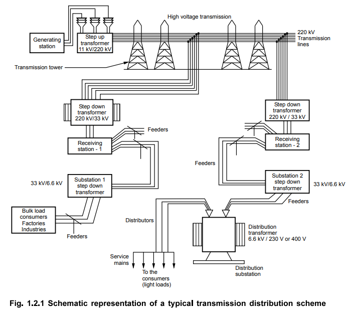
A scheme shows a generating station
which is located too far away from cities and towns. It is generating an
electrical power at 11 kV. It is required to increase this level for the
transmission purpose. Hence a step up transformer is used which steps up the
voltage level to 220 kV. This level may be 132 kV, 220 kV or more as per the
requirement.
Then with the help of transmission lines and the towers, the power is transmitted at very long distances. Design of the transmission lines is based on the factors like transmission voltage levels, constants like resistance, reactance of the lines, line performance, interference with the neighbouring circuits etc. Its mechanical features are strength of the supports, sag calculations, tension etc. Transmission of power by the overhead lines is very much cheaper. Similarly the repairs also can be carried out comparatively more easily. The transmission is generally along with additional lines in system of bare conductors is not practicable. In such cases insulated conductors are used in the form of underground cables, to give supply to the consumers. These cables are called service mains. This is called secondary distribution.
This is the complete flow of an
electrical power from the generating station to the consumer premises.
Let us study the line diagram of such a
typical scheme of transmission and distribution and discuss the various
components and voltage levels at the various stages in detail. The Fig. 1.2.2
shows the line diagram of a typical transmission and distribution scheme.
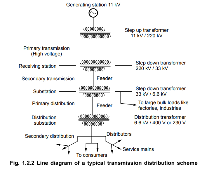
At the generating station, an electrical
power is generated with the help of three phase alternators running in
parallel. In the scheme shown, the voltage level is 11 kV but the voltage level
may be 6.6 kV, 22 kV or 33 kV depending upon the capacity of the generating
station. After the generating station, actual transmission and distribution
starts. The overall scheme can be divided into four sections which are,
1. Primary transmission :
It is basically with the help of overhead transmission lines. For the economic
aspects, the voltage level is increased to 132 kV, 220 kV or more, with the
help of step up transformer. Hence this transmission is also called high
voltage transmission. The primary transmission uses 3 phase 3 wire system.
2. Secondary transmission :
The primary transmission line continues via transmission towers till the
receiving stations. At the receiving stations, the voltage level is reduced to
22 kV or 33 kV using the step down transformer. There can be more than one receiving
stations. Then at reduced voltage level of 22 kV or 33 kV, the power is then
transmitted to various substations using overhead 3 phase 3 wire system. This
is secondary transmission. The conductors used for the secondary transmission
are called feeders.
3. Primary distribution :
At the substation the voltage level is reduced to 6.6 kV, 3.3 kV or 11 kV with
the help of step down transformers. It uses three phase three wire underground
system. And the power is further transmitted to the local distribution centres.
This is primary distribution, also called high voltage distribution. For the
large consumers like factories and industries, the power is directly
transmitted to such loads from a substation. Such big loads have their own
substations.
4. Secondary distribution :
At the local distribution centres, there are step down distribution
transformers. The voltage level of 6.6. kV, 11 kV is further reduced to 400 V
using distribution transformers. Sometimes it may be reduced to 230 V. The
power is then transmitted using distributors and service mains to the
consumers. This is secondary distribution, also called low voltage
distribution. This uses 3 phase 4 wire system. The voltage between any two
lines is 400 V while the voltage between any of the three lines and a neutral
is 230 V. The single phase lighting loads are supplied using a line and neutral
while loads like motors are supplied using three phase lines.
1. Components of Distribution
The distribution scheme consists of
following important components :
1. Substation : Transmission
lines bring the power upto the substations at a voltage level of 22 kV or 33
kV. At the substation the level is reduced to 3.3 kV or 6.6 kV. Then using
feeders, the power is given to local distribution centres.
2. Local distribution station :
It consists of distribution transformer which steps down the voltage level from
3.3 kV, 6.6 kV to 400 V or 230 V. Then it is distributed further using
distributors. This is also called distribution substation.
3. Feeders :
These are the conductors which are of large current carrying capacitor. The
feeders connect the substation to the area where power is to be finally
distributed to the consumers. No tappings are taken from the feeders. The
feeder current always remains constant. The voltage drop along the feeder is
compensated by compounding the generators.
4. Distributors :
These are the conductors used to transfer power from distribution centre to the
consumers. From the distributors, the tappings are taken for the supply to the
consumers. The voltage drop along the distributors is the main criterion to
design the distributors.
5. Service mains :
These are the small cables between the distributors and the actual consumer
premises.
The interconnection of feeders,
distributors and service mains is shown in the Fig. 1.2.3.
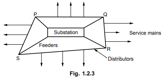
There is no tapping on feeders. PQ, QR,
RS and PS are the distributors which are supplied by the feeders. No consumer
is directly connected to the feeder. The service mains are used to supply the consumers
from the distributors. Tappings are taken from the distributors.
i) Sub mains :
The sub mains arrangement is shown in
the Fig. 1.2.4.
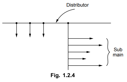
The service mains are small cables between
the distributors and the actual consumer premises. It may be possible that
various connections of consumers can be taken from one service mains. It is
called sub mains. In case of submains, the diameter of the conductors is more
than the normal service mains as more number of connections are taken from it.
Review Questions
1. Draw and explain the structure of typical electric power
system with various voltage levels.
AU : Dec -03, 07, 09, 13, 17, May-05, 06, 08, 09, 11, 12,
13, 14, 16, 17, 18, Marks 16
2. What is the difference between feeder, distributor and
service mains in a distribution scheme ?
AU : Dec.-04, 10, Marks 8
Transmission and Distribution: Unit I: Transmission Line Parameters : Tag: : - Structure of Power System
Related Topics
Related Subjects

Transmission and Distribution
EE3401 TD 4th Semester EEE Dept | 2021 Regulation | 4th Semester EEE Dept 2021 Regulation