Digital Logic Circuits: Unit V: VHDL
Structure of VHDL Module
• The main components of a VHDL description consists of following kinds of declarations : ■ Package (optional) ■ Entity ■ Architecture ■ Configuration (optional)
Structure of VHDL Module
AU
: Dec.-12, 17, May-15, 17
•
The main components of a VHDL description consists of following kinds of
declarations :
■
Package (optional)
■
Entity
■
Architecture
■
Configuration (optional)
•
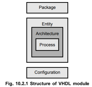
The Fig. 10.2.1 shows the relationship of these basic blocks of VHDL program. A
design may include any number of package, entity, architecture and
configuration declarations. It is important to note that the entity and
architecture blocks are compulsorily required; however, the package and
configuration blocks are optional.
1. Entity Declaration
•
It gives the specification of input/output signals to external circuitry. An
entity is modeled using an entity declaration and at least one architecture
body. An entity X, when used in another entity Y, becomes a component for the
entity Y. Entity gives interfacing between device and the other peripherals. An
entity usually has one or more ports, which are analogous to the pins on a
schematic symbol. All information must flow into and out of the entity through
the ports. Each port must contain name, data flow direction and type.
•
The syntax of a VHDL entity declaration is as shown below.
entity
entity_name is
port
(
signal_names : mode signal_type;
signalnames
: mode signal_type;
:
:
signal_names
: mode signal_type);
end
entity_name ;
The
following section describes the different elements of entity declaration.
entity_name
:
It is an identifier selected by the user to name the entity.
signal_names
:
It is a list of user selected identifiers to name external interface signals.
mode
:
The ports can be declared in four types which specify the signal direction.
in
:
This mode is used for a signal that is an input to an entity (value is read not
written).
out
:
It is used for a signal that is an output from an entity. The value of such a
signal can not be read inside the entity's architecture. But it can be read by
other entities those use it.
inout : It is used for a
signal that is both, an input to an entity and an output from the entity.
buffer
:
The signal is an output from the entity and its value can also be read inside
the entity's architecture.
signal_type
:
It is a built-in or user defined signal type.
For
example, there is a system having its inputs and outputs like rd, wr, ADD, x,
y, z, ad, al. The entity for this can be written as shown below.
entity
gate_logic is port (
wr
: in std_logic;
rd
: in std_logic;
ad
: inout std_logic_vector (7 downto 0) ;
ADD
: in std_logic_vector (0 to 3) ;
x,y,z
: out std_logic;
al
: buffer std_logic_vector (7 downto 0)
);
end
gate_logic ;
Here
rd, wr are inputs to the system so they are input ports. The ad is also input
signal but it is 8 bit so it is defined as vector (7 downto 0). It means 7 is
assigned to MSB of your signal and 0 is assigned to LSB of your signal.
Similarly x, y, z are output signals so they are defined as output ports. The
al is coming out and is defined as buffer signal, so that you can also read
this signal.
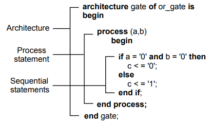
2. Architecture
•
Architecture specifies behavior, functionality, interconnections or
relationship between inputs and outputs. It is the actual description of the
design. An architecture consists of two portions : architecture declaration and
architecture body. An architecture body specifies the internal details of an
entity.
■
As a set of concurrent assignment
statements (to represent dataflow)
■
As a set of interconnected components
(to represent structure)
■
As a set of sequential assignment
statement (to represent behavior)
■
As any combination of above three.
•
The syntax for architecture is given below
architecture
architecture_name of entity_name is Declarations
begin
concurrent
statements;
sequential
statements;
end
architecture_name;
•
To design any system, first we have to write the entity. In the architecture, we
write architecture_name for that entity. In declaration part, types, signals,
constants, function definitions, procedure definitions, component definitions
etc. can be declared. The variables can also be declared here. VHDL variables
are similar to signals, except that they usually do not have physical
significance in a circuit. A variable declaration is similar to a signal
declaration, except that the 'variable' keyword is used as shown below.
variable
variable_names
: variables_type;
Example
:
3. Configuration Declaration
•
Configuration declarations may be used to associate particular design entities
to component instances (unique references to lower-level components) in a
hierarchical design, or to associate a particular architecture to an entity. As
their name implies, configuration declarations are used to provide
configuration management and project organization for a large design.
•
Example of configuration declaration :
library
CMOS_LIB, MY_LIB
Configuration
HA_BINDING of HALF_ADDER is
For
HA_STRUCTURE
For
XI : XOR2
Use
entity CMOS_LIB.XOR_GATE (DATAFLOW);
end for;
For
A1 : AND2
Use
configuration MY_LIB.AND_CONFIG;
end
for;
end
for;
end
HA_BINDING;
The
library statement makes library names CMOS_LIB and MY_LIB visible within the
configuration declaration.
HA_BINDING
is name of the configuration and it specifies a configuration for the
HALF_ADDER entity.
The
statement for HA_STRUCTURE specifies that the architecture body HA_STRUCTURE is
selected for this configuration.
•
As shown by the shaded portions there are two component bindings. The component
instantiation XI is bound to an entity represented by XOR-GATE entity
declaration and the DATAFLOW architecture body, which resides in the CMOS_LIB
design library. Similarly, component instantiation A1 is bound to a
configuration of an entity defined by the configuration declaration, with name
AND_CONFIG, residing in the MYJLIB design library.
4. Package Declaration
•
There are some declarations which are common across many design units. A
package is a convenient mechanism to store and share such declarations. It is
an optional design unit. A set of declarations contained in a package
declaration may be shared by many design units. It defines items that can be
made visible to other design units. A package is represented by :
■
Package declaration
■
Package body (optional)
Package
declaration
•
It defines the interface to the package. The syntax of a package declaration is
given below.
PACKAGE
package_name IS
type
declarations
subtype
declarations
constant
declarations
signal declarations
variable
declarations
subprogram declarations
file
declarations
alise
declarations
component declarations
attribute
declarations
attribute
specifications
disconnection
specifications
use
clauses
END
package_name;
•
The items declared in a package declaration can be accessed by other design
units by using the 'library' and 'use' clauses. This is explained in the
further section. The example of package declaration is given below.
package
MUX 4-to-l_package is
component
MUX 4-to-l
port
(MO, Ml, M2, M3 : IN STD_LOGIC;
s
: IN STD_LOGIC_VECTOR
(1
downto 0)
f
: OUT STD_LOGIC ;
end
component;
end
MUX 4-to-l_package;
5. Package Body
•
It contains the details of a package, that is the behavior of the subprograms
and the values of the deferred constants which are declared in a package
declaration. The package body may contain other declarations.
•
The syntax of it is as given below.
package
body package_name is
subprogram
bodies
complete
constant declarations
subprogram
declarations
type and subtype declarations
file
and alias declarations
use
clauses
end
package_name;
•
The name of the package must be same as the name of its corresponding package
declaration. If the package declaration does not have any subprogram or
deferred constant declarations, a package body is not necessary.
Review Questions
1. Explain structure of VHDL module.
2. Explain the declaration of an entity using example.
3. Explain the declaration of an architecture using example.
4. What is a package in VHDL ?
5. Explain package declaration with the help of example.
6. Explain the package body.
7. Briefly discuss the use of 'Packages’ in VHDL.
AU : Dec.-12, Marks 6
Digital Logic Circuits: Unit V: VHDL : Tag: : - Structure of VHDL Module
Related Topics
Related Subjects

Digital Logic Circuits
EE3302 3rd Semester EEE Dept | 2021 Regulation | 3rd Semester EEE Dept 2021 Regulation