Digital Logic Circuits: Unit II: Combinational Circuits
Subtractors
Logic diagram, Truth Table, Operation function, Example Problems | Combinational Circuits
• The subtraction consists of four possible elementary operations, namely,
Subtractors
•
The subtraction consists of four possible elementary operations, namely,
AU:
Dec.-14, 15, 16
0
- 0 = 0
0
- 1 = 1 with 1 borrow
1
- 0 = 1
1
- 1 = 0
•
In all operations, each subtrahend bit is subtracted from the minuend bit. In
case of second operation the minuend bit is smaller than the subtrahend bit,
hence 1 is borrowed. Just as there are half and full-adders, there are half and
full-subtractors.
1. Half Subtractor
•
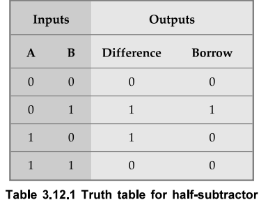
A half-subtractor is a combinational circuit that subtracts two-bits and
produces their difference. It also has an output to specify if a 1 has been
borrowed. Let us designate minuend bit as A and the subtrahend bit as B. The
result of operation A - B for all possible values of A and B is tabulated in
Table 3.12.1.
•
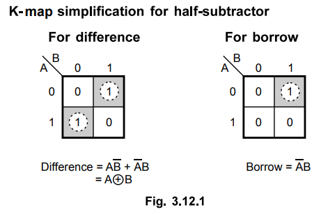
As shown in the Table 3.12.1, half-subtractor has two input variables and two
output variables. The Boolean expression for the outputs of half-subtractor can
be determined as follows.
Limitations
of half-subtractor :
•
In multidigit subtraction, we have to subtract two bits along with the borrow
of the previous digit subtraction. Effectively such subtraction requires
subtraction of three bits. This is not possible with half-subtractor.
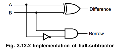
Logic
diagram
Ex.
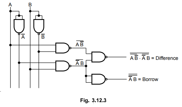
3.12.1 Draw half subtractor using NAND gates.
Sol.
:
For half subtractor :
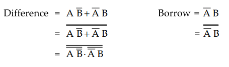
Implementation :
2. Full-Subtractor
A
full-subtractor is a combinational circuit that performs a subtraction between
two bits, taking into account borrow of the lower significant stage. This
circuit has three inputs and two outputs. The three inputs are A, B and B^,
denote the minuend, subtrahend and previous borrow, respectively. The two
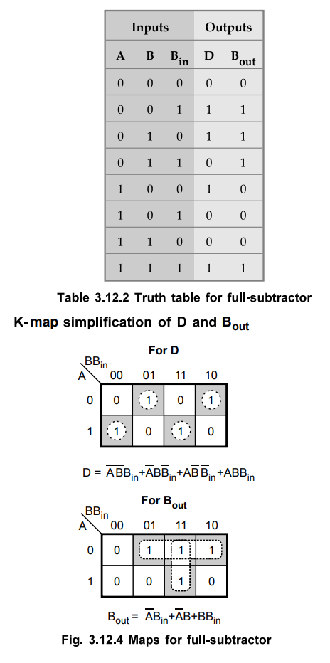
outputs, D and B represent the difference and output borrow, respectively. The
Table 3.12.2 shows the truth table for full-subtractor.
Logic
diagram
•
The Boolean function for D (difference) can be further simplified as follows :
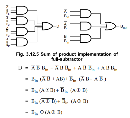
•
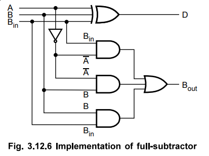
With this simplified Boolean function circuit for full-subtractor can be
implemented as shown in the Fig. 3.12.6
•
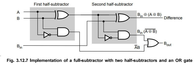
A full subtractor can also be implemented with two half-subtractors and one OR
gate, as shown in the Fig. 3.12.7. The difference output from the second half-subtractor
is the exclusive-OR of B. and the in output of the first half-subtractor, which
is same as difference output of full-subtractor.
• The borrow output for circuit shown in Fig. 3.12.6 can be given as,
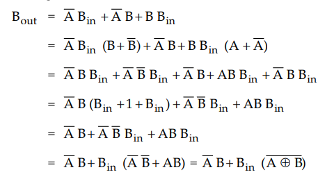
•
This Boolean function is same as borrow out of the full-subtractor. Therefore,
we can implement full-subtractor using two half-subtractors and OR gate.
Review Questions
1. Define half subtractor and full subtractor.
2. Explain the operation of a half subtractor with the help of
logic diagram and truth table.
3. Realize full-subtractor using K-map.
4. Design full-subtractor circuit and draw necessary truth
tables.
5. Explain how full subtractor can be designed by using two half
subtractor circuits. Draw the circuit diagram.
6. Design a full subtractor and implement it using logic gates.
7. Design a full subtractor and realise using logic gates. Also,
implement the same using half subtractors.
AU : Dec.-16, Marks 13
Digital Logic Circuits: Unit II: Combinational Circuits : Tag: : Logic diagram, Truth Table, Operation function, Example Problems | Combinational Circuits - Subtractors
Related Topics
Related Subjects

Digital Logic Circuits
EE3302 3rd Semester EEE Dept | 2021 Regulation | 3rd Semester EEE Dept 2021 Regulation