Electrical Machines II: UNIT I: c. Synchronization and Parallel Operation of Alternators
Synchronizing Power
Alternators
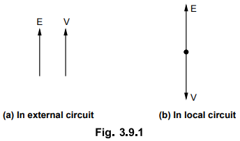
In the local circuit the two voltages E and V are in phase opposition while in the external circuit they are in the same phase.
Synchronizing Power AU
: Nov.-96, Oct.-97, 98, April-2000, 01, 04, May-01, 03, 08
Consider
an alternator connected to infinite bus bar. Let V be the bus bar voltage and E
be the e.m.f. induced in the alternator. The excitation of the alternator is
adjusted in such a way that E and V are equal in magnitude.
In
the local circuit the two voltages E and V are in phase opposition while in the external circuit they are in the same
phase. This is represented in the Fig. 3.9.1.
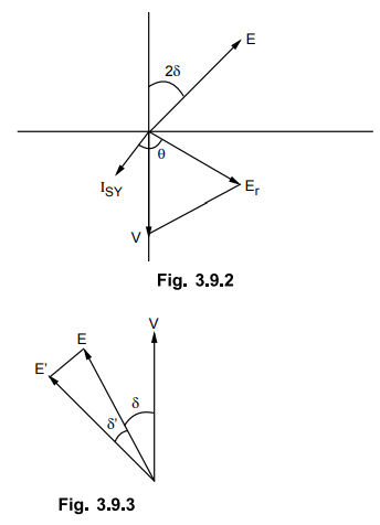
Consider
the alternator to be on no load. If by some means power input to machine is
decreased and its induced e.m.f. E will then lag behind V by say angle 28. Due
to this difference, E and V will not remain in exact phase opposition but will
give rise to resultant e.m.f. Er. This Er will act in the local circuit and a
synchronizing current ISY will start flowing in the local circuit. The
synchronizing current is given by,
ISY
= Er/Zs
ISY
is lagging behind Er by an angle θ given by,
θ
= tan-1(Xs/R)
R
is very very small it can be neglected.
θ
≈ 90°
The
angle 2δ is very very small and θ is approximately equal to 90° so the
synchronizing current IgY is almost in phase with V and in phase opposition
with E. So infinite bus bar will deliver some power to the alternator. As
current in the local circuit is always opposing to induced e.m.f. E, the
alternator will act as a synchronous motor. Thus synchronizing torque will be
developed which will try to accelerate the machine. Thus the angle 2 δ will go
on decreasing and resultant e.m.f. Er also goes on decreasing. Finally the two
e.m.f.s E and V will again be in phase opposition and the machine will now act
as an alternator in synchronism with bus bar.
Thus
the power which automatically comes into play and accelerates the machine which
was retarding and decelerates the machine which tries to accelerate is called
synchronizing power. This power will keep the machine in step with infinite bus
bar.
1. Expression for Synchronizing Power (PSY)
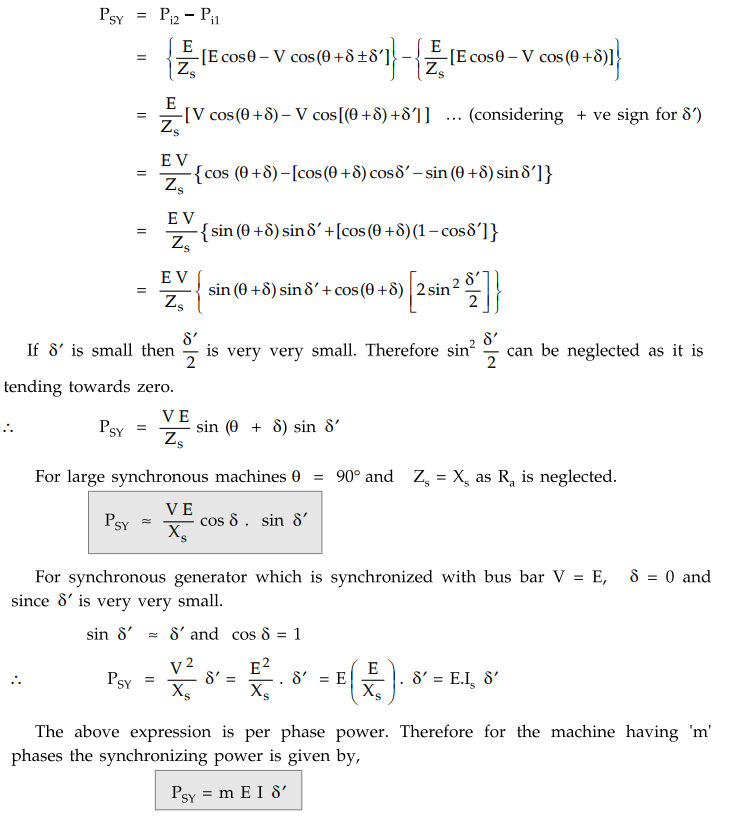
Consider
an alternator which is operating at an power angle δ i.e. E leads V by an angle δ
Let
power input of this alternator be increased suddenly so that it will now operate at a new power angle
given by δ + δ '. So the synchronizing
emf ESY will come into play and sends a circulating current given by
ISY = ESY / ZS. This current produces
synchronizing power. Now we will derive the expression for synchronizing power per phase.
Before
increasing the input of alternator, the power input Pil is given by,
Pil = E/ZS [E cos θ – V cos (θ + δ)
When
power angle δ has changed to δ ± δ ' (positive sign indicates acceleration
while negative sign indicates deceleration) the power input Pi2 is
given by,
Pi2
= E / ZS [E cos θ – V cos (θ+ δ ± δ)]
The
difference between these two power is nothing but synchronizing power PSY.
The
above expression is per phase power. Therefore for the machine having 'm'
phases the synchronizing power is given by,
PSY
= m E I δ'
2. Synchronizing Torque (TSY)
The
synchronizing torque TSY per phase in N-m when two alternators are
connected in parallel is given by,
When
alternator is connected to infinite bus bars then TSY is given as
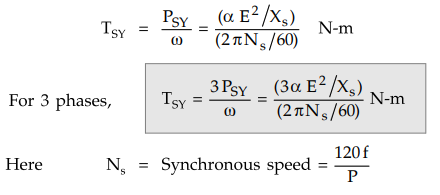
Here
Ns = Synchronous speed = 120f/P
3. Effect of Load on Synchronizing Power
When
the alternator is loaded then the expression for PSY is given as,
PSY
= ɑ E V /Xs
Here
V is bus bar voltage.
E
is alternator induced e.m.f. per phase.
E
= V + I Zs
The
corresponding phasor diagram is shown in the Fig.3.9.4
From
phasor diagram,

Example
3.9.1 A 700 KVA, 11 kV, 4 pole,3 phase star connected
alternator has percentage resistance and reactance as 1.5 and 14 respectively.
Determine synchronizing power per mechanical degree of displacement at full
load 0.8 p.f. lagging.
Solution:
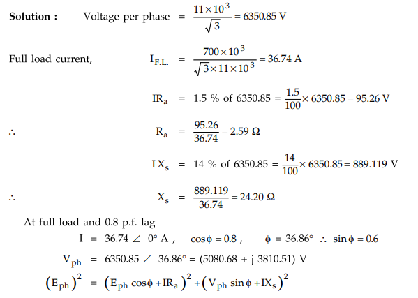
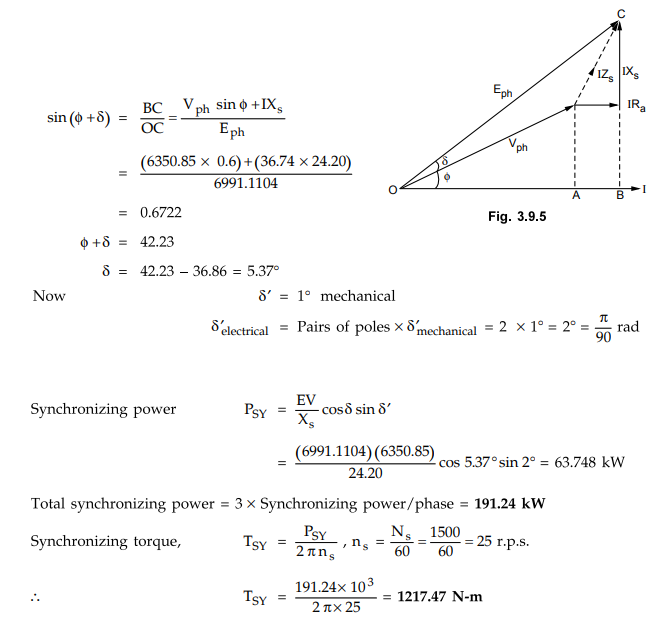
Using
the values, Eph = 6991.1104 volts.
The
phasor diagram is as shown in Fig. 3.9.5 Power angle, δ can be calculated as
follows.
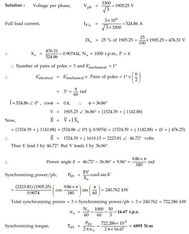
Example
3.9.2 A 3 MVA, 6 pole alternator runs at 1000 r.p.m.
on 3.3 kV bus bars. The synchronous reactance is 25 %. Calculate the
synchronizing power and torque per mechanical degree of displacement when the
alternator is supplying full load at 0.8 pf. lag. AU : Nov.-96,
April-2000, Marks 8
Example
3.9.3 A 5 MVA, 10kV, 1500 r.p.m. 3-phase, 50 Hz, 4
pole alternator is operating on infinite bus bar. Find the synchronizing power
per mechanical degree of angular displacement under no load condition Xs
= 20 %
Solution
:
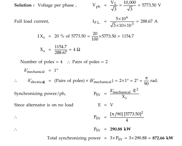
Example
3.9.4 A 5000 kVA, 10000 V, 1500 r.p.m., 50 Hz alternator
runs in parallel with other machines. Its synchronous reactance is 20 %. Find
the (1) no load (2) full load at power factor 0.8 lagging, synchronizing power
per unit, mechanical angle of phase displacement and calculate the
synchronizing torque if the mechanical displacement is 0.5°. AU
: May-08, Marks 12
Solution
:
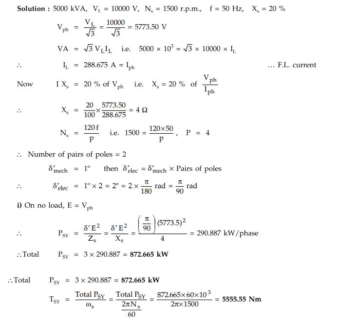
This
is synchronizing torque for 1° mechanical displacement .
For
0.5° mechanical displacement,
TSY
= 0.5 × 5555.55 = 2777.77 Nm
ii)
Full load, cos ϕ = 0.8 lagging, ϕ = cos-1 0.8 = 36.869°
I
= 288.675 ∠
0° A, V = 5773.5 ∠ 36.869°
V ...
I lags V
V
= 4618.8542 + j 3464.02 V
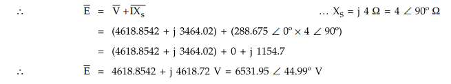
Thus
E leads I by 44.99° and V leads I by 36.869°
The
angle δ is the angle between E and V hence δ = 44.99° - 36.869° = 8.12°
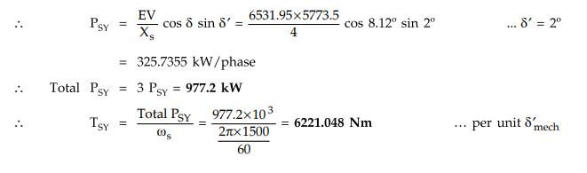
For
0.5° mechanical displacement,
TSY
= 0.5 × 6221.048 = 3110.524 Nm
Example
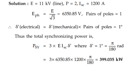
3.9.5 A 3 phase, 50 Hz, 2 pole alternator is excited
to generate the bus bar voltages of 11 kV at no load, Calculate the synchronizing
power per degree of mechanical displacement of the rotor. The machine is star
connected and the short circuit current for this excitation is 1200 amperes.
Neglect armature winding resistance.
Solution
:
E
= 11 kV (line), P = 2, Isc = 1200 A
Examples
for Practice
Example
3.9.6 A 10 MVA 3 phase alternator has an equivalent
short circuit reactance 20 %. Calculate the synchronizing power of the armature
per mechanical degree of phase displacement when running in parallel on a
10,000 V, 50 Hz bus bars at 1,500 r.p.m.
[Ans.:
1745.325 kW]
Example
3.9.7 A 700 kVA, 11 kV, 4 pole, 3 phase star connected
alternator has percentage resistance and reactance as 1.5 and 14 respectively.
Determine synchronizing power per mechanical degree of displacement at full
load 0.8 p.f. lagging.
[Ans.:
191.24 kW, 1217.47 N-m]
Example
3.9.8 Calculate the synchronizing power in kW for 1
mechanical degree of displacement at full load 0.8 power factor lagging for 3
phase, 2000 kVA, 6600 V, 50 Hz, 12 pole synchronous machine having a
synchronous reactance of 25 % and negligible resistance.
[Ans.:
961.48 kW]
Example
3.9.9 A 5 MVA, 11 kV, 50 Hz, 4-pole, star-connected
synchronous generator with synchronous reactance of 0.7 p.u. is connected to an
infinite bus. Find synchronizing power and the corresponding torque per unit of
mechanical angle displacement -
i)
At no load and ii) At full load of 0.8 p.f. lagging.
[Ans.:
i) 1587.3 N-m, ii) 2253.494 N-m]
Example
3.9.10 A 6.6 kV, 3 MVA, 3 phase, 50 Hz, 8 pole alternator
has synchronous reactance of 2.9 ohm and negligible resistance. When it is
operating on infinite bus, calculate the synchronizing power and the
corresponding torque per mechanical degree of phase displacement at
i)
No load ii) Full load 0.85 pf lag.
[Ans.:
1048.64 kW, 13.35 × 10³ N-m, 1158 kW, 14.74 × 10³ N-m]
Example
3.9.11 A 2000 kVA, 3 phase, 8 pole star connected
synchronous generator runs on 6000 volts, 50 Hz infinite bus bars. Find the
synchronizing power and synchronizing torque per mechanical degree of
displacement for full load at 0.8 p.f. lagging. The resistance of generator is
0.01 p.u. and synchronous reactance is 1.2 p.u.
[Ans.:
4.77°, 1255.6 kW, 15986.78 Nm]
Example
3.9.12 A 2 MVA, 3-phase, 8 pole, 750 rpm, sychronous
generator is operating on 6000 V bus bars. The synchronous reactance is 6
Q/phase. Find the synchronizing power and torque per mechanical degree at full
load and 0.8 pflag.
[Ans.:
502.248 kW, 6394.82 Nm]
Example
3.9.13 A 2 pole, 50 Hz, 3 phase, turbo alternator is
excited to generate the bus bar voltage of 11 kV on no load. The machine is
star connected and short circuit for this excitation is 1000 A. Calculate the
synchronizing power per degree of mechanical displacement of the rotor and the
corresponding synchronizing torque.
[Ans.:
332.52 kW, 1058.44 N-m]
Example
3.9.14 A 3 MVA, 6 pole alternator runs at 1000 r.p.m.
in parallel with other machine on 3.3 kV bus bars. The synchronous reactance is
20 %. Calculate the synchronizing power per mechanical degree of displacement and
the corresponding synchronizing torque.
[Ans.:
261.797 kW, 7500 N-m]
Review Question
1. Derive the expression for the synchronizing power when an
alternator is connected to infinite bus bar.
Electrical Machines II: UNIT I: c. Synchronization and Parallel Operation of Alternators : Tag: Engineering Electrical Machines - II : Alternators - Synchronizing Power
Related Topics
Related Subjects

Electrical Machines II
EE3405 Machine 2 EM 2 4th Semester EEE Dept | 2021 Regulation | 4th Semester EEE Dept 2021 Regulation