Transmission and Distribution: Unit V: (a) Distribution Systems
Techniques of Voltage Control
Reactive Power Injection - Static VAR Generator - Rotating VAR Generator - Control by Tap Changing Transformer
Question : 1. Discuss the methods of voltage control in transmission line.
Techniques of Voltage
Control
The electrical energy generated in the
generating station is supplied to the consumers through the network of
transmission and distribution. For satisfactory operation of various loads at
the consumer end, it must be supplied with fairly constant voltage. In order to
avoid erratic operation or malfunctioning of appliances at the consumer end,
the voltage at the consumer end must be controlled and kept within permissible
limits.
Because of change in load on the power
system, the voltage at user end goes on changing. With increase in load, the
voltage drop in alternator synchronous impedance, transmission line,
transformer impedance, feeders and distributors increases. With decrease in
load, these drops increase. These variations in voltages are undesirable and
must be kept within proper limits. This limit is generally ± 6 % of declared voltage
at consumer end. In this section we will discuss some of the methods which are
used for voltage control.
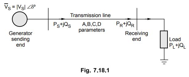
Consider the two bus system shown in
Fig. 7.18.1. Let the line is having negligible resistance and consists of
series reactance. For fixed sending end voltage and at the given receiving end
voltage, the real and reactive powers are given by,
As the real power demanded by the load
must be delivered by line
PR = PL
The varying real power demanded by load
is met by consequent changes in torque angle δ.
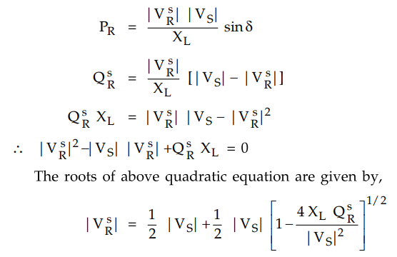
The reactive power of the line should
remain fixed at QSR when |VS| is fixed for the
specified |VSR|. The line will hence operate with
specified receiving end voltage
for only one value of QL given
by
QL = QSR
But the loads in actual practice are
normally lagging in nature such that VAR demand QL may exceed VSR
from above equation for VSR it can be seen that for QL
> QSR the receiving end voltage must change from the
specified value |VR| to some value | VSR | to meet
demanded |VR|. Hence
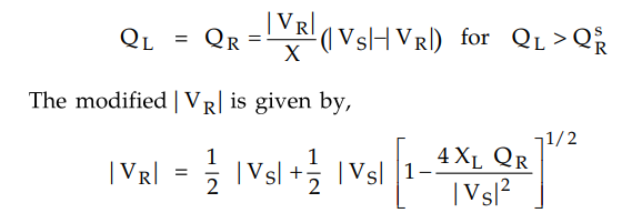
The above value |VR| is less
than | VSR | for QL > QSR
similarly |VR| is greater than | VSR | for QL
> QSR
It can be seen that under light load
condition the line capacitance causes VAR demand to become negative which
results in receiving end voltage exceeding the sending end voltage.
The various methods employed for voltage
control include
i) Use of series capacitors
ii) Use of shunt capacitors
iii) Use of static VAR sources
iv) Use of shunt reactors
v) Tap changing of transformers.
1. Reactive Power Injection
It can be seen from the previous section
that to maintain the receiving end voltage at its specified value, a fixed
amount of VARs (QSR) must be drawn from the line. A local
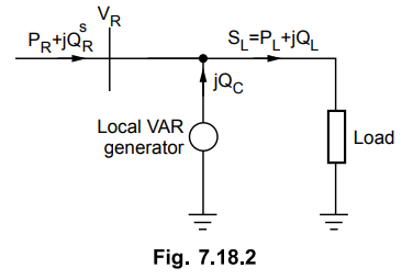
VAR generator must be used for conditions of varying VAR demand QL. The
VAR balance equation at the receiving end is given as,
QSR + QC
= QL
The fluctuations in QL are
absored by local VAR generator in such a way tht total VAR drawn by the line
remain fixed at QSR The receiving end voltage is
therefore maintained at fixed value of | VSR |. This is
shown in Fig. 7.18.2.
This is nothing but compensation of VAR
which can be made automatic by taking signal from VAR meter installed at
receiving end. Normally two types of VAR generators are used in practice viz
static type and rotating type.
2. Static VAR Generator
It consists of bank of 3 phase static
capacitors and / or inductors. From the Fig. 7.18.3 we can see that XC
is reactance per phase of the capacitor bank.
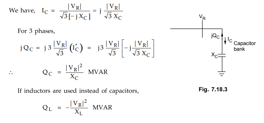
When the load on power system is high
then positive VARs are required. In this case capacitor banks are used while
when light load is there on the system, negative VARs are required then
inductor banks are switched on.
If it is required to have a smooth
control of VAR then Silicon Controlled Rectifier (SCR) may be used. With the
considerable harmonics say fifth harmonics may result in overloading of
capacitors. At harmonic frequencies there is chance of series resonance to
occur. The capacitors act as short circuit when they are switched on.
It can also be seen that the variation
of QC is proportional to V2R. So under heavy
load condition when voltage decreases QC may not prove to be
effective.
3. Rotating VAR Generator
It is nothing but a synchronous motor
running at no load. The excitation of this motor can be adjusted over a wide
range. In overexcited condition it supplies positive
VARs whereas gives negative VARs when
underexcited. The synchronous motor running under this condition is called
synchronous condenser. It is shown in Fig. 7.18.4.
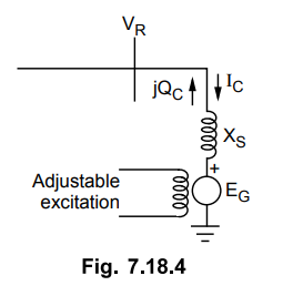
The synchronous condenser is connected
to the receiving end bus bars and runs under no load condition. It takes
negligibly small real power such that EG and VR are
almost in phase. XS is the synchronous reactance of the motor. The
motor is having negligible resistance.
We have,
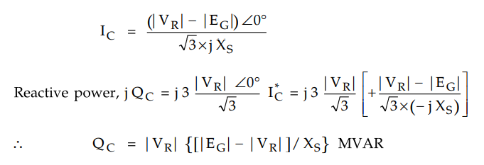
When |EG | > | VR
| the machine is overexcited and provides positive VARs whereas |EG|
< | VR |, the machine is underexcited the machine is underexcited
and provides negative VARs. Thus positive and negative continuously adjustable
VARs can be obtained with this method. At a given escitation the VAR injection
is less sensitive to changes in |VR , As |VR | decreases,
|EG | - | VR | increases with corresponding smaller
reduction in QC.
From the above discussion it can be
concluded that rotating VAR generator is more effective than static VAR
generator. Hence it may be preferred. But its limiting factors are economic
considerations, installation and maintainance problems.
4. Control by Tap Changing Transformer
This method is employed for narrow range
of voltage control. Due to VAR demands of load, the receiving end voltage tends
to decrease which can be raised by simultaneous tap changing on sending and
receiving end transformers. It can be done either on no load or on load. Thus
there are two types of tap changing transformers viz on load and on no load.
Consider the operation of a transmission
line with a tap changing transformer at each end as shown in Fig. 7.18.5.
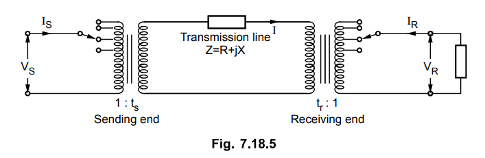
The impedances of the transformers are
taken alongwith line impedances. These tap changing transformers do not control
the voltage by controling the flow of VARs but by changing the transformation
ratio, the voltage in the secondary circuit is varied and voltage control is achieved. Let ts and
tr are the fractions of the nominal transformation ratios i.e. tap
ratio/nominal ratio. The product of ts and tr is taken as
unity for ensuring uniformity in voltage level.
From the Fig. 7.18.5,
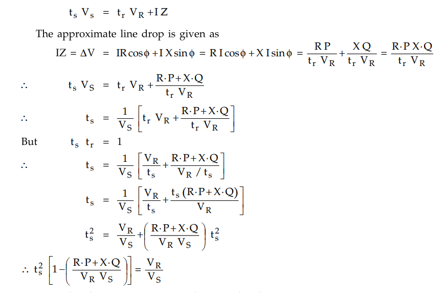
From the above equation it can be seen that
for particular values of VR and VS and the load
requirements P and Q the value of ts can be determined.
Review Question
1. Discuss the methods of voltage control in transmission line.
Transmission and Distribution: Unit V: (a) Distribution Systems : Tag: : Reactive Power Injection - Static VAR Generator - Rotating VAR Generator - Control by Tap Changing Transformer - Techniques of Voltage Control
Related Topics
Related Subjects

Transmission and Distribution
EE3401 TD 4th Semester EEE Dept | 2021 Regulation | 4th Semester EEE Dept 2021 Regulation