Digital Logic Circuits: Unit V: VHDL
Testbenches
Types, Writing, Syntax, Advantages | VHDL
• Before processing a design by synthesis tool, the designer usually wants to verify that the design performs according to the specification. This is almost always done by running a simulation.
Testbenches
AU
: Dec.-l0, May-16
•
Before processing a design by synthesis tool, the designer usually wants to
verify that the design performs according to the specification. This is almost
always done by running a simulation. Simulating a design requires generation of
test data and observation of simulation results. This process is done by use of
a VHDL module that is referred to as testbench. It verify the functionality of
the design at each step in the HDL synthesis - based methodology.
•
Test benches can be very simple, for example, just providing a sequence of test
inputs to the circuit overtime. Sometimes this sequence represents a simple
periodic waveform used to describe a system clock. However, sometimes it can be
a very complex one and stored in a file. The testbench has to provide a reading
of text vectors from the file, and also the writing of results to a report
file. Even more, it can be required to provide reference vectors and compare
them with the output of the unit under test during simulation to provide a pass
or fail indication.
•
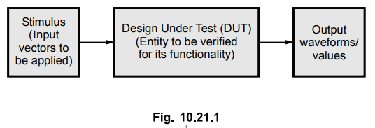
The Fig. 10.21.1 shows the typical structure of testbench. As shown in the Fig.
10.21.1, the test bench instantiates the 'Design Under Test' (DUT) / 'Unit
Under Test' (UUT). The testbench provides the necessary input stimulus (input
vectors to be applied) to the DUT and examines the output from the DUT.
•
The objectives of the testbench can be summarized as :
•
Instantiate the DUT/UUT,
•
Generate stimuli waveforms and apply them to the DUT/UUT in the form of test
vectors during simulation,
•
Generate reference waveforms and compare them with the output from the DUT/UUT
model during simulation.
•
Provide pass/fail indications
1. Types of Testbenches
The
types of writing testbenches are :
•
Stimulus only : This testbench contains only the
stimulus driver and DUT; does not contain any results verification.
•
Full testbench : This testbench contains stimulus
driver, known good results and results comparison.
•
Simulator specific : This testbench is written in a
simulator-specific format.
•
Hybrid testbench : This testbench combines techniques from
more than one testbench style.
•
Fast testbench : These testbenches are written to get
ultimate speed from simulation, i.e. they are optimized for speed.
• The Table 10.21.1 shows the advantages and disadvantages of above discussed test benches.

2. Writing a Testbench
•
When writing a testbench, the DUT (Design Under Test) is included as a
component in the testbench model. Testbench is written as an entity just like
any other VHDL model with an architecture body which includes DUT as a
component.
Syntax
of testbench
entity
tb is
end
tb;
architecture
tb of tb is
component
DUT port
(
port_name: mode type)
end
component;
Local
signals;
begin
M1:
DUT port map {association list);
process
begin
signal
assignments to create stimulus (generating test_vectors)
applying
test vectors to DUT;
[verify
or compare or store results;]
end
process;
end
tb;
•
The entity declaration for a testbench is usually empty. This is because the
test bench itself does not have any inputs or outputs. Test vectors are
generated and applied to the unit under test within the test bench. Note that
it is illegal to have an architecture body without an entity declaration.
•
The architecture part has a component with is DUT with the same name and
matching ports. Its declaration is needed in the test bench in order to pull
the entity into the test bench. In order that the VHDL simulator can bind the
design entity to the component, the names and types of the ports must match
between the entity and the component.
•
The executable part includes the statements to generate test_vectors (the
values applied as stimulus to inputs.)
•
With VHDL, there are three ways to generate test vectors :
1.
Generation by an algorithm : It includes,
a)
simple assignments of signals,
b)
continuous loops for periodic signals or
c)
procedures for complex signal patterns (procedural stimuli)
2.
Generation from constants stored in an array
3.
Generation from constants stored in a separate file
•
Once the test vectors are available, they are applied to DUT. Finally, output
is verified or written to the result file or error is reported. It is important
to note that monitoring of output values in the testbench is optional. We can
simply observe the output as waveform in the simulation windows. If the output
is to be compared against the expected values, a set of expected values for
output parameters is required.

The
waveforms generated for the SEL, A, B, C and D signals are as shown in Fig.
10.21.2.

Advantages
of using Testbenches
1.
Testbench provide the user with the capability to test the DUT thoroughly
through simulation.
2.
Testbench allows to simulate DUT under a variety of test conditions including
correct and faulty test inputs.
3.
Testbench makes it easier to create a wide range of stimulus inputs,
particularly with respect to timing of input signals.
4.
Its structure is well defined and flexible to accept changes if there are
changes in the circuit under test.
5.
The output generated by testbench can be observed as waveforms or can be stored
as values for comparison against expected values or for later analysis or to
compare two simulations.
6.
It gives an idea about the timing requirements of the DUT (Design under test).
7.
The testbench approach is useful for post-fit verification.
Review Questions
1. Write a note on testbenches.
2. State the types of testbenches and compare them.
3. Explain the syntax of testbench with the help of an example.
4. State the advantages of using test benches.
5. Write the VHDL code to realize a 4 - bit parallel binary
adder with structural modelling and write the test bench to verify its
functionality.
AU : May-16, Marks 10
Digital Logic Circuits: Unit V: VHDL : Tag: : Types, Writing, Syntax, Advantages | VHDL - Testbenches
Related Topics
Related Subjects

Digital Logic Circuits
EE3302 3rd Semester EEE Dept | 2021 Regulation | 3rd Semester EEE Dept 2021 Regulation