Electrical Machines II: UNIT I: c. Synchronization and Parallel Operation of Alternators
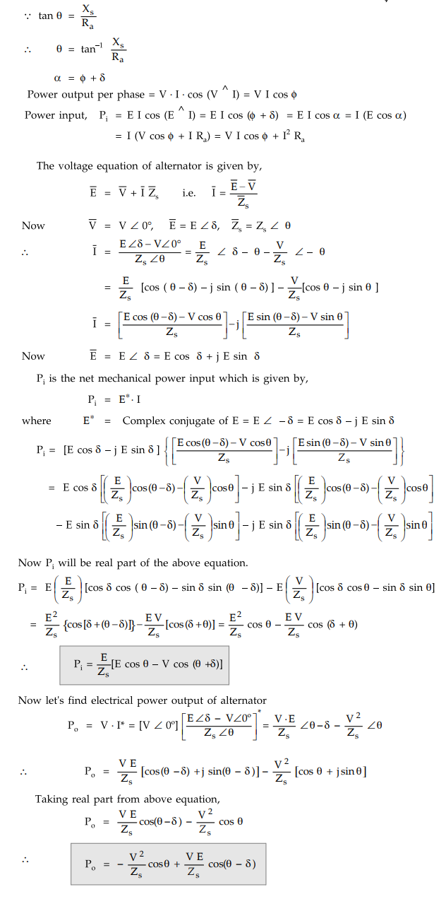
Theory of Cylindrical Rotor Machines
Alternators
With increase in δ, power increases and with decrease in 8, power decreases. Power in case of synchronous machine depends on the angle δ. This angle δ is called power angle.
Theory of Cylindrical Rotor Machines
Let
us consider the phasor diagram for alternator for lagging p.f. as shown in the
Fig. 3.6.1.

Let
E = E.M.F induced in each phase
V
= Terminal voltage
ϕ
= Phase angle between voltage and current
δ
= Power angle
Ra
= Resistance of armature
Xs
= Synchronous reactance of alternator
Key Point : With increase in δ, power increases and with decrease in 8, power decreases. Power in case of synchronous machine depends on the angle δ. This angle δ is called power angle.
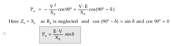
In
case of large synchronous machines, Xs >>> Ra
θ
= tan-1(Xs/Ra) ≈ 90° (if armature resistance
is neglected)
Substituting
θ = 90°, in above equation the net electrical power output from alternator is
given by,
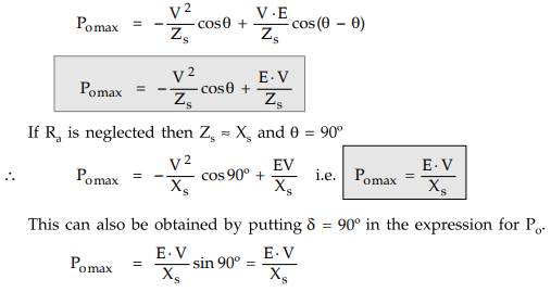
1. Maximum Power Output
Now
let's find the maximum power output developed by alternators by taking
derivative of Po w.r.t 8 and equating it to zero to get the condition for
maximum power.

Substituting
this condition for maximum power in the expression for output power,
2. Power Factor at Maximum Power Condition
Consider the phasor diagram as shown in the Fig. 3.6.2.
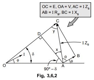
For
Pomax, θ = δ and cos ϕ is leading hence I leads V by ϕ.
AD
is perpendicular drawn from A on OC. In triangle OAD,
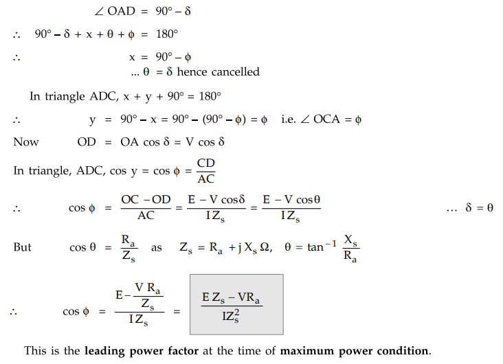
This
is the leading power factor at the time of maximum power condition.
3. Operating Characteristics
The
operating characteristics of a synchronous machine are seen under variable
excitation and load condition. One of the parameter is kept constant while
other is varied for studying these characteristics. The resistance of armature
is neglected as it does not change the characteristics significantly. So the
corresponding circuit is as shown in the Fig. 3.6.3.

The
phasor diagram corresponding to above condition is shown in the Fig. 3.6.4.

Power
delivered to the infinite bus per phase is given by,
Pi
= V – Ia cos ϕ
From
the above phasor diagram it can be seen that
∠ OBA = 90 - ϕ
∠ OBC = 180 - (90 - ϕ) =
90 + ϕ
From
∆ OBC,

Key Point : The above power
is the electrical power exchanged with bus bars. Angle 8, between E and V is
known as power angle.
4. Power Angle Characteristics
As
seen previously,
Pi
= EV sin δ / Xs
The
relationship between Pi and δ is known as power angle
characteristics of the machine. It is shown in the Fig. 3.6.5.

The
maximum power occurs at δ = 90°. Beyond this point the machine falls out of
step and loses synchronism. The machine can be taken upto Pimax only by gradually
increasing the load. This is known as the steady state stability limit of the
machine. The machine is normally operated at 8 much less than 90°.
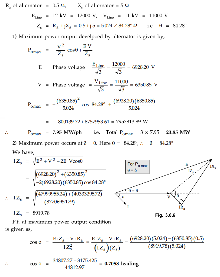
Example
3.6.1. A 20 MVA, 3 phase star connected alternator with
an impedance of 5 Ω and a resistance of 0.5 Ω is operating in parallel with
constant voltage 11 kV busbars. If its field current is adjusted to give an
excitation voltage of 12 kV, calculate :
1)
The maximum power output from the alternator and
2)
The power factor under maximum conditions.
Solution
:
MVA rating of alternator is 20 MVA.
Example
for Practice
Example
3.6.2 For a cylindrical rotor alternator working at
lagging power factor, show that tan δ = Ia(Xscos ϕ - Rasin
ϕ)
/ Vt + Ia(Xs sin ϕ + Ra cos ϕ)
The
symbols having their usual meanings.
Review Question
1. Derive the expression for the output power of cylindrical
rotor alternator connected to infinite bus in terms of excitation voltages, bus
bar voltage and load angle.
Electrical Machines II: UNIT I: c. Synchronization and Parallel Operation of Alternators : Tag: Engineering Electrical Machines - II : Alternators - Theory of Cylindrical Rotor Machines
Related Topics
Related Subjects

Electrical Machines II
EE3405 Machine 2 EM 2 4th Semester EEE Dept | 2021 Regulation | 4th Semester EEE Dept 2021 Regulation