Electric Circuit Analysis: Unit IV: Three phase circuits
Three phase power measurement - two-watt meter method
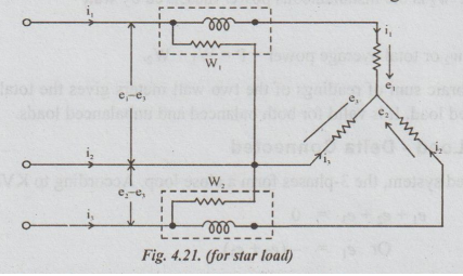
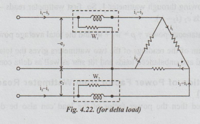
This method is applied usually for measuring the electrical power in 3-phase, 3-wire circuit. The load may be balanced or unbalanced. It may be connected either in delta or star.
THREE PHASE POWER MEASUREMENT - TWO-WATT METER METHOD
This
method is applied usually for measuring the electrical power in 3-phase, 3-wire
circuit. The load may be balanced or unbalanced. It may be connected either in
delta or star.
The
current coils of 2 watt meters are inserted in two of the lines and voltage
coil of each wattmeter is connected from its own current coil to the line in
which no wattmeter has been connected. The connections of watt meters in this
method are shown in Fig.4.21 & 4.22.
Let
e1, e2 and e3 be the voltages of the three
loads at particular instant and i, iz and is be the currents of the three loads
i.e., these voltages and currents are called instantaneous values. Hence, the
power at the instant under consideration is equal to the sum of their products,
regardless of power factor
i.e.,
Instantaneous power = P = e1i1 + e2i2
+ e3i3 ... (1)
1. Case (1) Load Star Connected
Since
all the three-phases meet at a star point, application of KCL yields
Here
i1 = the instantaneous current flowing through the current coil of
wattmeter. (e1 - e3) = the instantaneous potential difference
across voltage coil of wattmeter 1.
Therefore
i (e1- e3) = w1. w1 is the
instantaneous power measured by wattmeter 1.
I2
= The instantaneous currents flowing through the current coil of wattmeter 2.
(e2- e3) = the instantaneous potential difference across
the voltage coil of wattmeter 2.
I2
(e2 – e3) = w2. W2 is the
instantaneous power measured by watt meter 2.
Hence
p = w1 + w2 or total average power = P = W1 +
W2.
Hence,
the algebraic sum of readings of the two watt meters gives the total power in
the 3-phase, 3-wire star connected load. It is valid for both balanced and
unbalanced loads.
2. Case (2) Load - Delta Connected
In
delta connected system, the 3-phases form a close loop. According to KVL,
e1
+ e2 + e3
Or
e1 = -(e2 + e3 )
From
equation (1),
-
e3 is the instantaneous p.d. across the voltage coil of wattmeter 1.
(i1
– i3 ) the current flowing through wattmeter 1. So, first
wattmeter reads - e3 (i - i3). Similarly, the second wattmeter reads e2
(i2 - i1).
Hence,
the total instantaneous power = p = w1 + w2 and the total
average power = P = W1 + W2.
Thus,
the algebraic sum of the readings of the two wattmeters gives the total power
of the circuit. It is true for both balanced and unbalanced loads and for star
as well as delta connected systems.
3 (a) Determination of Power Factor from Wattmeter Readings (Valid Only for Balanced Loads)
If
the load is balanced then the power factor of the load can also be determined
from the 2 wattmeter readings.
The
vector diagram for a balanced star connected inductive load is shown in
Fig.(4.23)
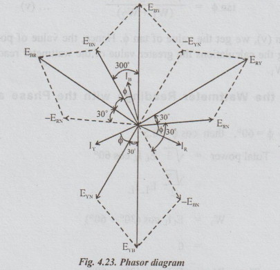
The
circuit coil of wattmeter 1 is connected in R-phase. The voltage coil of
wattmeter 1 is connected between R - phase and Y - phase.
Reading
of wattmeter 1 = W1.
=
|ERY| IR × cosine of the angle between ERY and
IR
W1
= ERY. IR COS (30+ϕ)
=
EL. IL cos (30+ϕ) ... (i)
The
current coil of wattmeter 2 is connected in B-phase. Voltage coil of wattmeter
2 is connected between B and R-phases. The angle between EBR and I, is equal to
(30+ϕ)
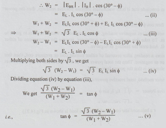
From
the equation (v), we get the value of tan o. Hence, the value of power factor
cos o can be calculated. In making the calculations the greater value of the
wattmeter readings is usually taken as W2 and the other as W1.
(b)
Variation of the Wattmeter Readings with the Phase angle & and hence Cosϕ
Case
(1): When ϕ = 60°, then cos ϕ = 0.5
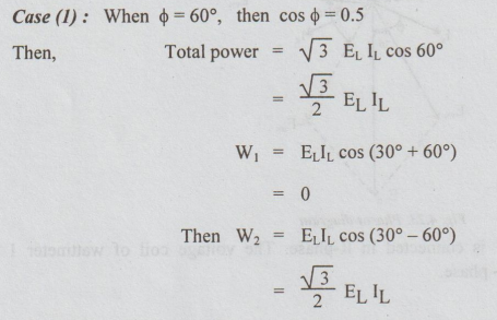
Hence
one wattmeter will read zero and the other will read the total power. In other
words, we can conclude as below:
In
the 2 wattmeter method, if one of the wattmeters reads zero reading, the power
factor must be 0.5. Here we assume that both wattmeters are fault - free.
Case
(2): if ϕ < 60°. Then cos o is more than 0.5. In this
case, both watt meters indicate positive readings.
In
other words, we can conclude that if both wattmeters indicate positive
readings, then the power factor is more than 0.5.
Case
(3): If ϕ > 60°, then cos o is less than 0.5.
In
this case, the wattmeter 1 gives negative reading. The pointer of this
wattmeter tries to go on to the left side of zero point. To take this reading
on the wattmeter, reverse the connections of either current coil or voltage
coil. And treat the reading as negative.
i.e.,
If wattmeter I shows a reading after reversal of either current coil or
pressure coil, then that watt meter reading is taken as negative. Then the
total power will be W2-W1. If one of the watt meters reads negative then the
inference is that the power factor < 0.5.
[Note:
In the 2 wattmeter method, total reactive power can also be found. Refer
equation (iv)]
Total
reactive Power = √3 EL IL sin
=
√3 (W2 – W1)
Electric Circuit Analysis: Unit IV: Three phase circuits : Tag: : - Three phase power measurement - two-watt meter method
Related Topics
Related Subjects

Electric Circuit Analysis
EE3251 2nd Semester 2021 Regulation | 2nd Semester EEE Dept 2021 Regulation