Electric Circuit Analysis: Two Mark Question and Answers
Two Mark Question and Answers set - 5
Electric Circuit Analysis
Electric Circuit Analysis: Two Mark Question and Answers
101.
When do the two wattmeters read equal in the two wattmeter method of
three-phase power measurement ?
Ans:
When the power factor is unity, both wattmeters will indicate equal readings.
102.
How can a wattmeter be used to measure reactive power?
Ans:
In case of balanced three-phase circuit, the reactive power can be determined
by using one wattmeter. The current coil of the wattmeter is connected in one
line and its pressure coil is connected across the other two lines.
Let
the reading of wattmeter be Wr
Then
the total reactive power = √3 Wr
103.
When does one wattmeter read zero in the two-wattmeter method of three-phase
power measurement?
Ans:
When the power factor is 0.5, one of the wattmeters indicates zero reading.
104.
Give the three-phase power expression in terms of phase values.
Ans:
Total average power = 3 | Vϕ | Iϕ | cos ϕ
where,
Vϕ = phase voltage
Iϕ
= phase current
cos
ϕ = power factor.
ϕ
= angle between phase voltage and phase current
105.
What are coupled circuits?
Ans:
Two circuits are said to be coupled, when atleast a part of the electrical
energy supplied to one circuit is transferred to the other.
106.
Define self-inductance. What is its unit?
Ans:
The self-inductance of a coil is defined as the flux linkage in that coil per
unit current in itself. Its unit is henry.
i.e.,
L = Nϕ / I
where
N is no. of turns, ϕ is the flux in webers and I is the current in amperes.
L
is also defined as weber turns per ampere current in the same coil.
107.
Write the expression for effective inductance of the series connected magnetically
coupled coils.
Ans:
For
cumulative coupling,
effective
inductance L = L1 + L2 + 2M
For
differential coupling,
total
inductance L = L1 + L2 - 2M
where
L1, L2 are self inductances of the two coils. M is the
mutual inductance between the two. L is the effective inductance.
108.
The effective inductance of the parallel connected magnetically coupled coils
is less for differential connection than cumulative one. State True or False.
Ans:
True.
109.
Give the expression for critical coefficient of coupling for a singly tuned
circuit.
Ans:
1
/ √ Q1 Q2
Here,
Q1, Q2 are quality factors of primary and secondary
windings of single tuned circuits.
110.
Define coefficient of Coupling.
Ans:
Coefficient of coupling is defined as ratio of mutual inductance to the
geometric mean of the self inductances. i.e.,
K
= M / √L1 L2
It
is also defined as follows. Let there be two coils coupled magnetically. Let
the flux produced in coil 1 be 1, when the coil 1 is excited by a voltage
source. Let 12 be the flux linked in coil 2.
So,
K = ϕ12 / ϕ1 also K = ϕ21 / ϕ2
111.
What is meant by double tuned coupled circuits?
Ans:
A double tuned coupled circuit is one in which the capacitor is present in both
primary and secondary circuits.
It
may be a series double-tuned or parallel-double-tuned. A series doubly tuned
transformer has a series capacitor in the primary winding and has a capacitor
connected in parallel across the secondary.
A
parallel doubly tuned transformer has a capacitor connected in parallel with
the primary winding and a capacitor in parallel with the secondary winding.
112.
What is the maximum possible mutual inductance of two inductively coupled
coils, with self-inductances L1 = 25 mH, L2 = 100mH?
Ans:
maximum
M = √L1 L2
=
√25 × 10-3 × 100 × 10-3
=
√25 × 10-4
=
50 mH
113.
Two inductors are connected as shown in the figure. What is the value of the
effective inductance of the combination?
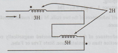
Ans:
The current is entering one coil at the dot and leaving the other coil at the
dot. So, the coupling is differential.
The
effective inductance = L1 + L1 - 2M
=
3 + 5 - 2(2)
=
4 Henrys
114.
Define mutual inductance and write an expression for it.
Ans:
The mutual inductance is defined as the ability of one coil to produce emf in
second coil, by induction when the current flows in the first coil. This action
is reciprocal. It is quantitatively measured in terms of coefficient of mutual
inductance. M is defined as weber turns in one coil per ampere current in the
other coil.
i.e.,
M = N2 ϕ2 / I1 = N1 ϕ1 /
I2 Henrys
115.
Give the applications of double-tuned circuits.
Ans:
It is widely used in the intermediate frequency amplifiers in receivers.
116.
State the dot rule for coupled circuit.
Ans:
1.
If both currents enter dotted ends of coupled coils or if both currents enter
undotted ends, then the signs on the M-terms will be same as the signs on the
L-terms.
2.
If one current enters a dotted end and the other an undotted end, the signs on
the M-terms will be opposite to the signs on the L-terms.
117.
Sketch the frequency response of double-tuned circuit.
Ans:
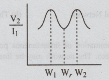
118.
Define critical coupling.m
Ans:
Critical coupling is given by
KC
= Mc / √ L1 L2
Here
Mc is called critical value of mutual inductance. At this value of
mutual inductance, the output voltage or voltage amplification in a double
tuned coupled circuit is maximum.
119.
Sketch the frequency response of a single tuned circuit.
Ans:
120.
State superposition theorem.
Ans:
"In a linear circuit containing more than one source, the current that
flows at any point or the voltage that exists between any two points is the
algebraic sum of the currents or the voltages that would have been produced by
each source taken separately with all other sources removed."
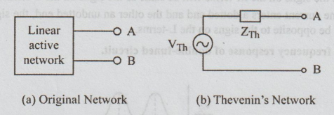
121.
State Thevenins theorem.
Ans:
Any linear active network with output terminals A, B as shown in fig. (a) can
be replaced by a single voltage source (VTh = Voc) in series
with a single impedance (ZTh = Zi). Job at
VTh
is the Thevenin's voltage. It is the
voltage between the terminals A and B on open circuit condition. Hence it is called
open circuit voltage and is denoted by Voc
122.
State Tellegen's theorem.
Ans:
"In any network the summation of instantaneous powers or the summation of
complex powers of sinusoidal sources is zero. The network may be linear,
non-linear, passive or active and time invariant or varying."
For
instantaneous power the theorem may be expressed mathematically as
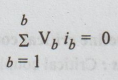 where b is the number of branches in the network.
123.
State reciprocity theorem.
Ans:
In a linear, bilateral network a voltage source V volts in a branch gives rise
to a current I in V another branch. If V is applied in the second branch the
current in the first branch will be I. This V/I is called transfer impedance or
resistance.
124.
State the substitution theorem.
Ans:
"Any branch of network can be replaced by a different branch, as long as
its potential and current remain unchanged. When the original branch is
passive, either a voltage source or a current source is usually used for the
substituted branch."
125. State Norton's theorem.
Ans:
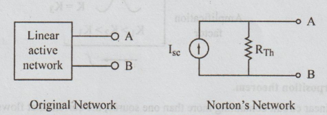
"Any
linear active network with output terminals A, B as shown in the figure can be
replaced by a single current source. ISC (IN) in parallel
with a single impedance ZTh (Zn) = RTh ( = RN)"
ISC
is the current through the terminals AB of the active network when shorted. ZTh
is the Thevenin's impedance.
Electric Circuit Analysis: Two Mark Question and Answers : Tag: : Electric Circuit Analysis - Two Mark Question and Answers set - 5
Related Topics
Related Subjects

Electric Circuit Analysis
EE3251 2nd Semester 2021 Regulation | 2nd Semester EEE Dept 2021 Regulation