Basic Civil & Mechanical Engineering: UNIT I: b. Structural engineering
Types of stresses and strains
The basic types of stress and strain are given below: 1. Tensile Stress and Tensile Strain 2. Compressive Stress and Compressive Strain 3. Shear Stress and Shear Strain 4. Bending Stress and Bending Strain
TYPES OF STRESSES AND STRAINS
The
basic types of stress and strain are given below:
1.
Tensile Stress and Tensile Strain
2.
Compressive Stress and Compressive Strain
3.
Shear Stress and Shear Strain
4.
Bending Stress and Bending Strain
1. TENSILE STRESS AND TENSILE STRAIN
Tensile
Stress (ft)
Fig.
1(i) shows a bar subjected to the action of a pulling load P along the axis.
The load P tends to pull apart the particles of the bar and to increase the
length of the bar in the direction of application of the load.
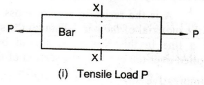
Pulling
load P is called Tensile Load or Tensile Force. The corresponding stress
is called Tensile Stress.
Fig.
1(ii) shows the resisting forces R at section XX. Assuming the bar to be
in equilibrium, the resisting force R = pulling load P.
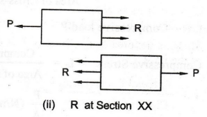
Fig.
1(iii) shows a cross-sectional element of the bar subjected to tensile stress ft.
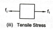
A
is the resisting area or cross-sectional area of the bar. Though the stress is
shown by a line in this Figure, it should be assumed as applied over the entire
cross-section of the bar.
Tensile
Stress = ft = Resisting Force / Area of Cross-section = R / A
But,
R = Tensile load P
Tensile
Stress = ft = Tensile Load / Area of Cross-section
=
P / A (N/m2)
Tensile
Strain (et)
See
Fig. 2. Let I be the initial length of the bar before the application of
tensile load. After the application of tensile load P, the bar elongates
or extends by an elementary length = dl.
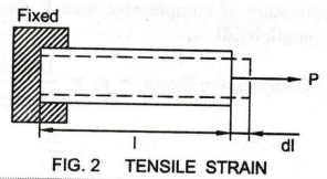
Tensile
Strain = et = Increase in length / Original length = dl / l
2. COMPRESSIVE STRESS AND COMPRESSIVE STRAIN
Compressive
Stress (fc)
Fig.
3(i) shows a bar acted upon by an axial load P that tries to compress
the bar. The load P compresses the particles of the material of the bar
and decreases the length of the bar in the direction of application of the
load. The load P is called Compressive Load or Compressive Force. The
corresponding stress is called Compressive Stress.
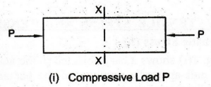
Fig.
3(ii) shows the resisting forces R at section XX. Assuming the body to
be in equilibrium, the resisting force R= compressive load P.
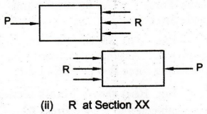
Fig.
3(iii) shows a cross-sectional element of the body subjected to compressive
stress fc.
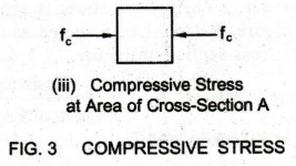
A
is the resisting area or cross sectional area of the material of the bar.
Though the stress is shown by a line in this Figure, it should be assumed as
applied over the entire cross-section of the bar.
Compressive
Stress = fc
Resisting
Force / Area of Cross-section = R / A
But,
R = Compressive load P
Compressive
Stress = fc = Compressive Load / Area of Cross-section
=
P / A (N/m2)
Compressive
Strain (ec)
See
Fig. 4. Let l be the initial length of the bar before the application of
compressive load. After the application of compressive load P, the bar
decreases in length by dl.
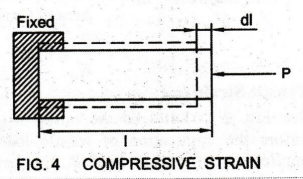
Compressive
Strain = ec = Decrease in length / Original length
=
dl / 1
3. SHEAR STRESS AND SHEAR STRAIN
Shear
Stress (q)
See
Fig. 5(A). It shows a riveted joint subjected to the action of two equal and
opposite forces P. P acts tangentially to the resisting section XX, causing
sliding of the particles one over the other.
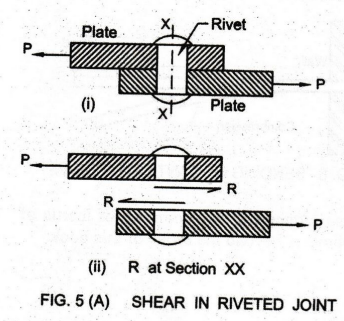
Section
XX of the rivet holds the plates together and resists the tendency of the
plates to get sheared-off (torn-off). In this example, the rivet section is
said to develop shear stress.
See
Fig. 5(B). Consider a square block ABCD of length 1, height h and width of 1
unit. The bottom face AB is fixed. A force P is applied tangentially along the
top face DC.
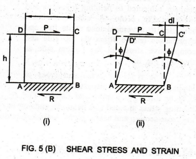
To
keep the block in equilibrium, the fixed surface at the bottom will offer an
equal and opposite reaction R towards left as shown. Therefore, the
block is made to slide sideward to the new position D'C' as shown in Fig. 5
(B). The applied transverse load P is called the Shear Force.
Shear
Force P tends the upper part of the block to slide towards right along
any of the horizontal planes considered in the block. But, the block offers an
internal resistance against the sliding. This internal resistance is called
Shear Resistance. This shear resistance per unit crosssectional area is called
Shear Stress q.
Shear
Force Shear Stress = q = Shear Force / Area of Cross-section = P/ A (N/m2)
Shear
Strain (es)
See
Fig. 5(B). The top of the block is distorted by an amount di due to the shear
force. Let the angle of distortion be φ. as shown. The intensity of this
angular deformation is proportional to the distance of the fiber from the fixed
base.
Shear
Strain is defined as the ratio of the transverse (horizontal) displacement to
the distance from the fixed lower base. It is denoted as es.
Shear
Strain = es = Transverse Displacement / Distance from the fixed Base = dl / h =
tan φ
In
this equation, φ is the angle in radian through which the block is distorted by
the shear force. The shear deformation is so small that there will be no error
in approximating tan φ as φ.
Shear
Strain = e = tan φ = φ, where φ is the angle of distortion in radians.
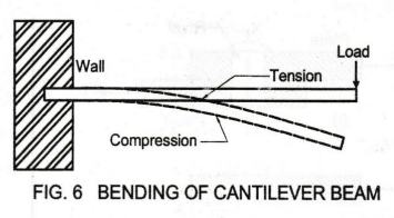
4. BENDING STRESS AND BENDING STRAIN
The
most common or simplest structural element subjected to bending moments and
shear is the beam. A cantilever beam subjected to a vertical load at its free
end experiences tensile stress on top side and compressive stress on the bottom
side as shown in Fig. 6.
The
types of beam and types of loading on beam are discussed in Chapter on
Beams, Columns and Lintels. The bending stress induced in a beam depends on
the bending moment, area of moment of inertia of the cross-section and beam
height. A discussion on the above is beyond the scope of this book.
5. OTHER TYPES OF STRAIN
Longitudinal
Strain or Linear Strain: The deformation of a body in the
direction of force per unit original longitudinal dimension is called the
Longitudinal Strain or Linear Strain.
Longitudinal
Strain = Change in Length in the
direction of Force / Original Length
Lateral
Strain: When an elastic body is subjected to an axial
stress, within the Elastic Limit (discussed later), it deforms not only in the
direction of stress but also in the lateral direction. The lateral deformation
per unit original lateral dimension is called the Lateral Strain. But the
lateral strain is opposite in nature to the longitudinal strain.
For
example, under the action of an axial tension, the length of the body
increases. But, its breadth and thickness decrease. Under axial compression,
the length decreases but the lateral dimensions, breadth and thickness,
increase.
Lateral
Strain = Increase / Decrease in Lateral Dimension / Original Lateral Dimension
Volumetric
Strain: It is the ratio of change in volume to original
volume of an object.
Volumetric
Strain = Change in Volume / Original Volume = dv /
Basic Civil & Mechanical Engineering: UNIT I: b. Structural engineering : Tag: : - Types of stresses and strains
Related Topics
Related Subjects

Basic Civil and Mechanical Engineering
BE3255 2nd Semester 2021 Regulation | 2nd Semester EEE Dept 2021 Regulation