Digital Logic Circuits: Unit V: VHDL
VHDL Description for Counters
1. VHDL Code for a Four-bit Up Counter 2. VHDL Code for a 4-bit Up Counter using Integer Signals 3. VHDL Code for a 4-bit Down Counter 4. VHDL Code for a 3-bit Asynchronous Counter 5. VHDL Code for Asynchronous Counter with GLITCH 6. VHDL Code for Synchronous Mod-6 Counter 7. 4-bit Unsigned Up Counter with Asynchronous Load from Primary Input 8. 4-bit Unsigned Up Counter with Synchronous Load with a Constant 9. Structural Description of 3-bit Synchronous Binary Counter
VHDL Description for Counters
1. VHDL Code for a Four-bit Up Counter
•
The VHDL code for a four-bit up-counter having Reset and Enable inputs is given
below. Since the counter is 4-bit, four flip-flops are used in a counter and
they are represented by the signal named 'Count'. Clock and Reset signals are
included in the sensitivity list. The process statement includes an
asynchronous reset of Count if Reset input (Resetn) is 0. At the end of the
code, the Q outputs are assigned the value of Count.
LIBRARY
IEEE;
USE
IEEE.std_logic_1164.all;
USE
IEEE.std_logic_unsigned.all;
ENTITY
upctr IS
PORT(
Clock,Resetn.EN : IN STDLOGIC;
Q
: OUT STD_LOGIC_VECTOR (3 DOWNTO 0));
END
upctr;
ARCHITECTURE
Behavior OF upctr IS
SIGNAL
Count: STD_LOGIC_VECTOR(3 DOWNTO 0);
BEGIN
PROCESS(Clock,
Resetn)
BEGIN
IF
Resetn = '0' THEN
Count
< = "0000";
ELSIF(Clock'EVENT
AND Clock = '1') THEN
IF
EN = '1' THEN
Count<
=Count+1;
ELSE
Count<
=Count;
END
IF;
END
IF;
END
PROCESS;
Q<=
Count;
END
Behavior;
2. VHDL Code for a 4-bit Up Counter using Integer Signals
•
This section gives the VHDL code for a four-bit up counter having parallel load
and reset inputs. In this code, we are declaring parallel data P and output of
the counter Q as an INTEGER type. Since the counter is four bit, the range of P
as well as Q is (24 = 16) 0 to 15. These signals represent four-bit
quantities. Output Q is defined in a buffer mode which represents outputs of
the flip-flops. The process statement specifies an asynchronous reset of Q if
Resetn is 0. On positive clock edge, if 'Load' input is 1, then the flip-flops
in the counter are loaded in parallel from P inputs. If 'Load' input is 0, then
the counter output Q is incremented. The Q outputs have the buffer mode.
LIBRARY
IEEE;
USE
IEEE.std_logic_1164.all;
ENTITY
upctr IS
PORT(P
: IN INTEGER RANGE 0 TO 15 ;
Clock,
Resetn, : IN STD_LOGIC;
Q
: BUFFER INTEGER RANGE 0 TO 15);
END
upctr;
ARCHITECTURE
Behavior OF upctr IS
BEGIN
PROCESS(Clock,
Resetn)
BEGIN
IF
Resetn = '0' THEN
Q
<=0;
ELSIF(Clock'EVENT
AND Clock = I1) THEN
IF
Load='T THEN
Q<=P;
ELSE
Q<=Q
+ 1;
END
IF;
END
IF;
END
PROCESS;
END
Behavior;
3. VHDL Code for a 4-bit Down Counter
•
This section gives a VHDL code for a four-bit down counter with parallel load.
The starting count is declared as a GENERIC parameter in this code so that it
can be changed easily. In this code, we are calling it as a 'MOD'. On the
positive clock edge, if 'Load' input is 1, then the counter is loaded with the
count MOD-1. If the 'Load' is 0, then the Count is decremented. At the end of
the code, the Q outputs are assigned the value of Count.
LIBRARY
IEEE;
USE
IEEE.std_logic_1164.all;
ENTITY
downctr IS
GENERIC(MOD
: INTEGER :=8;
PORT
(Clock, Load, EN : IN STD_LOGIC;
Q
: OUT INTEGER RANGE 0 TO MOD-1);
END
downctr;
ARCHITECTURE
Behavior OF downctr IS
SIGNAL
Count : INTEGER RANGE 0 TO MOD-1;
BEGIN
PROCESS
BEGIN
WAIT
UNTIL (Clock'EVENT AND Clock = 1);
IF
EN = '1' THEN
IF
LOAD = THEN
Count
<= MOD-1;
ELSE
Count
<= Count-1
END
IF;
END
IF;
END
PROCESS;
Q<=
Count;
END
Behavior;
4. VHDL Code for a 3-bit Asynchronous Counter
•
Let us see the VHDL code for 3-bit asynchronous counter with active high Reset
and Set inputs.
LIBRARY
IEEE;
USE
IEEE.STD_LOGIC_1164.ALL;
ENTITY
Counterl IS
PORT(
CLK
: IN STD_LOGIC;
Resetp
: IN STDLOGIC;
Setp
: IN STD_LOGIC;
Q
: INOUT STD_LOGIC_VECTOR (2 DOWNTO 0)
);
END
Counterl;
ARCHITECTURE
AsynchCntr OF Counterl IS
BEGIN
PROCESS(CLK,
Resetp, Setp, Q)
BEGIN
IF
Resetp='O' THEN
Q<="000";
ELSIF
Setp='O' THEN
Q<="111";
ELSIF
CLK ='0' AND CLK'event THEN
Q(0)<
= NOT Q(0);
END
IF;
IF
Q(0)='0' AND Q(0)'EVENT THEN
Q(l)<
= NOTQ(l);
END
IF ;
IF
Q(1)='O' AND Q(1)'EVENT THEN
Q(2)<
= NOT Q(2);
END
IF ;
END
PROCESS;
END
Asynch_Cntr;
5. VHDL Code for Asynchronous Counter with GLITCH
•
Let us see the VHDL code for an asynchronous mod-6 Counter with GLITCH and
active low Reset and Set inputs.
LIBRARY
IEEE;
USE
IEEE.STD_LOGIC_1164.ALL;
ENTITY
Counter2 IS
PORT(
CLK : IN STD_LOGIC;
Resetn
: IN STD_LOGIC;
Setn
: IN STD_LOGIC;
Q
: INOUT STD_LOGIC_VECTOR (2 DOWNTO 0)
);
END
Counter2;
ARCHITECTURE
Asynch_Glitch OF Counter2 IS
BEGIN
PROCESS(CLK,
Resetn, Setn, Q)
VARIABLE
Qtemp: STD_LOGIC_VECTOR (2 DOWNTO 0);
BEGIN
IF
Resetn='0' THEN
Qtemp
:="000";
ELSIF
Setn='0' THEN
Qtemp
:="111";
ELSIF
CLK = '0' AND CLK'event THEN
Qtemp(0)
:= NOT Qtemp(0);
END
IF;
IF
Q(0)='0' AND Q(0)'EVENT THEN
Qtemp(l)
:= NOT Qtemp(l);
END
IF;
IF
Q(1)='O' AND Q(1)'EVENT THEN
Qtemp(2)
:= NOT Qtemp(2);
END
IF;
Q
< = Qtemp;
IF
Qtemp > "101" THEN
Qtemp
:= "000";
Q
< = "000" AFTER 2ns;
END
IF;
END
PROCESS;
END
Asynch_GIitch;
6. VHDL Code for Synchronous Mod-6 Counter
•
Let us see the VHDL code for synchronous mod-6 Counter with active low Reset
and Set inputs.
LIBRARY
IEEE;
USE
IEEE.STD_LOGIC_1164.ALL;
USE
IEEE ,STD_LOGIC_unsigned.ALL;
ENTITY
Counter3 IS
PORT(
CLK : IN STDLOGIC;
Resetn
: IN STD_LOGIC;
Setn
: IN STD_LOGIC;
Q
: INOUT STD_LOGIC_VECTOR (2 DOWNTO 0)
);
END
Counter3;
ARCHITECTURE
Synch_Cntr OF Counter3 IS
BEGIN
PROCESS(CLK,
Resetn, Setn)
VARIABLE
Qtemp: STD_LOGIC_VECTOR (2 DOWNTO 0);
BEGIN
IF
Resetn='0' THEN
Qtemp
:= "000";
ELSIF
Setn='0' THEN
Qtemp
:= "111";
ELSIF
CLK ='l' AND CLK'event THEN
IF
Qtemp < 5 THEN
Qtemp
:= Qtemp + 1;
ELSE
Qtemp
:= "000";
END
IF;
END
IF;
Q
< = Qtemp;
END
PROCESS;
END
Synch_Cntr;
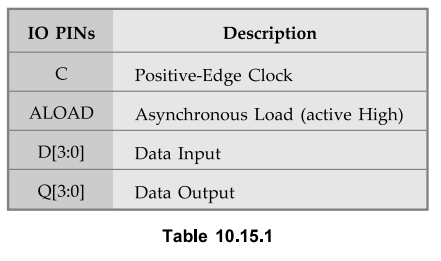
7. 4-bit Unsigned Up Counter with Asynchronous Load from Primary Input
•
The pin description of 4-bit unsigned up counter is as shown in the Table
10.15.1.
•
The VHDL code for a 4-bit unsigned up counter with asynchronous load from
primary input is as follows.
LIBRARY
IEEE;
USE
IEEE.std_logic_1164.all;
USE
IEEE.std_logic_unsigned.all;
ENTITY
counter IS
PORT(C,
ALOAD : IN std_logic;
D
: IN std_logic_vector(3 downto 0);
Q
: OUT std_logic_vector(3 downto 0));
END
counter;
ARCHITECTURE
archi OF counter IS
signal
tmp: std_logic_vector(3 downto 0);
BEGIN
PROCESS
(C, ALOAD, D)
BEGIN
IF
(ALOAD = 'T) THEN
tmp
<= D;
ELSIF
(C'event and C=’T) THEN
tmp
<= tmp + 1;
END
IF;
END
PROCESS;
Q
< = tmp;
END
archi;
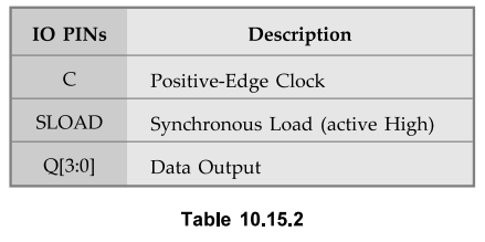
8. 4-bit Unsigned Up Counter with Synchronous Load with a
Constant
•
The pin description of 4-bit unsigned up counter is as shown in the Table
10.15.2.
•
The VHDL code for a 4-bit unsigned up counter with synchronous load with a
constant is as follows.
LIBRARY
IEEE;
USE
IEEE.std_logic_1164.all;
USE
IEEE.std_logic_unsigned.all;
ENTITY
counter IS
PORT(C,
SLOAD: IN std_logic;
Q
: OUT std_logic_vector(3 downto 0));
END
counter;
ARCHITECTURE
archi OF counter IS
signal
tmp: std_logic_vector(3 downto 0);
BEGIN
PROCESS
(C)
BEGIN
IF
(C'event and C=’T) THEN
IF
(SLOAD=’l') THEN
tmp
< = "1010";
ELSE
tmp
<= tmp + 1;
END
IF;
END
IF;
END
PROCESS;
Q
< = tmp;
END
archi;
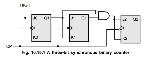
9. Structural Description of 3-bit Synchronous Binary Counter
•
The Fig. 10.15.1 shows the logic diagram of 3-bit synchronous binary counter.
The Listing 10.15.1 gives the structural description of 3-bit synchronous
binary counter.
Listing
10.15.1 : VHDL description for 3-bit synchronous binary counter,
library
ieee;
use
ieee.std_logic_1164.all;
entity
counter is
port
( CP : in std_logic;
Q,
Qbar: buffer std_logic_vector(2 downto 0));
end
counter;
architecture
cnt_3Bit of counter is
component
and2
port
( II, 12 : in std_logic;
O1
: out std_logic);
end
component;
component
JK_FF
port
( II, 12, 13 : in std_logic;
Ol,
02 : buffer std_logic);
end
component;
for
all : and2 use entity work.two_input (and2_4);
for
all : JKFF use entity work.JKFF (FF);
signal
J2 std_logic;
begin
A1
: and2 port map (Q(0), Q(l), J2);
JK1
: JK_FF port map ('1', '1', CP, Q(0), Qbar(0));
JK2
: JK FF port map (Q(0), Q(0), CP, Q(l), Qbar(l));
JK3
: JK_FF port map (J2, J2, CP, Q(2), Qbar(2));
end
cnt_3Bit;
Review Questions
1. Write a VHDL code for asynchronous and synchronous counters.
2. Write the VHDL code for mod 6 counter.
3. Write the VHDL code to realize a decade counter with
behavioural modelling.
Digital Logic Circuits: Unit V: VHDL : Tag: : - VHDL Description for Counters
Related Topics
Related Subjects

Digital Logic Circuits
EE3302 3rd Semester EEE Dept | 2021 Regulation | 3rd Semester EEE Dept 2021 Regulation