Digital Logic Circuits: Unit V: VHDL
VHDL Description of Flip-Flops
1. Behavioral Description of D Flip-Flop using IF-THEN Statements 2. Behavioral Description of D Flip-Flop using WAIT-UNTIL Statement 3. Behavioral Description of D Flip-Flop with Asynchronous Reset/Clear 4. Behavioral Description of D Flip-Flop with Synchronous Reset/CIear 5. Behavioral Description of DFF with a Negative-Edge Clock and Asynchronous Clear 6. Behavioral Description of DFF with Positive-Edge Clock and Synchronous Set 7. Behavioral Description of DFF with Positive-Edge Clock and Clock Enable 8. Structural Description of Pulse Triggered SR Flip-Flop 9. Structural Description of Pulse Triggered D Flip-Flop 10. Structural Description of JK Flip-Flop 11. Behavioral Description of JK Flip-Flop using Case Statement 12. Description of D Flip-Flop using VHDL Function
VHDL Description of Flip-Flops
AU
: Dec.-11, 15, 17, May-15
1. Behavioral Description of D Flip-Flop using IF-THEN Statements
•
Consider a positive edge-triggered D flip-flop. We know that the D flip-flop is
similar to D-latch except 'clock pulse' is used instead of enable input. So
VHDL code for D flip-flop is same as that of D-latch with two exceptions.
•
i) The Clk signal is the only signal that can cause a change in the Q output.
So only Clk signal is to be given in the process sensitivity list.
•
ii) Positive edge triggering is required at the Clk input.
•
In VHDL, 'attribute' refers to a property of an object, such as a signal. For D
flip-flop, two conditions are required at the Clk input. First is, change in
the Clk signal and second is, Clk should be equal to one. We are using 'EVENT
attribute to indicate any change in the Clk signal and Clock = 1 condition.
Thus, positive edge triggering condition can be obtained by logically ANDing
Clock'EVENT condition with the condition, Clock = 1.
•
The VHDL code for a positive-edge-triggered D flip-flop is given below.
LIBRARY
IEEE;
USE
IEEE. std_logic_1164.all;
ENTITY
DFF IS
PORT
(D, Clock : IN STD_LOGIC;
Q
: OUT STD_LOGIC);
END
DFF;
ARCHITECTURE
Behavior OF DFF IS
BEGIN
PROCESS
(Clock)
BEGIN
IF
ClockEVENT AND Clock = ‘1’
Q
< = D;
END
IF;
END
PROCESS;
END
Behavior;
2. Behavioral Description of D Flip-Flop using WAIT-UNTIL
Statement
•
In the previous code, we have used IF-THEN statement. The similar code can be
written using WAIT-UNTIL statement. This statement has the same effect as
IF-THEN statement. In this case, the sensitivity list is omitted. The VHDL code
for a positive-edge triggered D flip-flop using a WAIT-UNTIL statement is given
below. The WAIT-UNTIL construct implies that the sensitivity list includes only
the clock signal.
LIBRARY
IEEE;
USE
IEEE.std_logic_1164.all;
ENTITY
DFF IS
PORT(D,
Clock : IN STD_LOGIC;
Q
: OUT STD_LOGIC);
END
DFF;
ARCHITECTURE
Behavior OF DFF IS
BEGIN
PROCESS
BEGIN
WAIT
UNTIL Clock'EVENT AND Clock = 1';
Q
< = D;
END
PROCESS;
END
Behavior;
3. Behavioral Description of D Flip-Flop with Asynchronous
Reset/Clear
•
In this section we are describing a D flip-flop with an asynchronous active-low
Reset (Clear) input. When Reset input is equal to 0, the flip-flop's Q output
is set to 0. The VHDL code for a D flip-flop with asynchronous Reset/Clear
input is given below.
LIBRARY
IEEE;
USE
IEEE.std_logic_1164.all;
ENTITY
DFF IS
PORT(D,
Resetn, Clock : IN STD_LOGIC
Q
: OUT STD_ LOGIC)
END
DFF;
ARCHITECTURE
Behavior OF DFF IS
BEGIN
IF
Resetn = ‘0’ THEN
Q
< = ‘0’
ELSIF
Clock EVENT AND Clock = ‘1’ THEN
Q<=D;
END
IF;
END
PROCESS;
END
Behavior;
4. Behavioral Description of D Flip-Flop with Synchronous Reset/CIear
•
Consider a positive edge triggered D flip-flop. The reset signal of the
flip-flop is acted upon only when a positive clock edge arrives. The VHDL code
for a D flip-flop with synchronous Reset/Clear input is given here.
LIBRARY
IEEE;
USE
IEEE.std_logic_1164.all;
ENTITY
DFF IS
PORT(D,
Resetn, Clock : IN STDLOGIC;
Q
: OUT STD_LOGIC);
END
DFF;
ARCHITECTURE
Behavior OF DFF IS
BEGIN
PROCESS
BEGIN
WATT
UNTIL Clock'EVENT AND Clock = '1';
IF
Resetn='O' THEN
Q<
= 0';
ELSE
Q<=D;
END
IF;
END
PROCESS;
END
Behavior;
•
This code generates the circuit shown in Fig. 10.14.1.

5. Behavioral Description of DFF with a Negative-Edge Clock and
Asynchronous Clear
•
The input/output pin description of the D flip-flop is as shown in Table
10.14.1.
•
The equivalent VHDL code for a DFF with a negative-edge clock and asynchronous
clear is as follows.

LIBRARY
IEEE;
USE
IEEE.std_logic_1164.all;
ENTITY
flop IS ""
PORT(C,
D, CLR : IN stdjogic;
Q
: OUT stdjogic);
END
flop;
ARCHITECTURE
archi OF flop IS
BEGIN
PROCESS
(C, CLR)
BEGIN
IF
(CLR = ‘l')THEN
Q
<= ‘O';
ELSIF
(C'event and C=’0’)THEN
Q
< = D;
END
IF;
END
PROCESS;
END
archi;
6. Behavioral Description of DFF with Positive-Edge Clock and Synchronous Set
•
The input/output pin description of the D flip-flop is as shown in Table
10.14.2.

•
The equivalent VHDL code for the D flip-flop with a positive-edge clock and
synchronous set is as follows.
LIBRARY
IEEE;
USE
IEEE.std_logic_1164.all;
ENTITY
flop IS
PORT(C,
D, S : IN std_logic;
Q
: OUT std_logic);
END
flop;
ARCHITECTURE
archi OF flop IS
BEGIN
PROCESS
(C)
BEGIN
IF
(C'event and C='l') THEN
IF
(S='l’) THEN
Q
< = ‘1’;
ELSE
Q
<= D;
END
IF;
END
IF;
END
PROCESS;
END
archi;
7. Behavioral Description of DFF with Positive-Edge Clock and
Clock Enable
•
The input/output pin description of the D flip-flop is as shown in Table
10.14.3.

•
The equivalent VHDL code for the D flip-flop with a positive-edge clock and
clock enable is as follows.
LIBRARY
IEEE;
USE
IEEE.std_logic_1164.all;
ENTITY
flop IS
PORT(C,
D, CE : IN std_logic;
Q
: OUT stdlogic);
END
flop;
ARCHITECTURE
archi OF flop IS
BEGIN
PROCESS
(C)
BEGIN
IF
(C’event and C=’T) THEN
IF
(CE = ’T) THEN
Q
<= D;
END
IF;
END
IF;
END
PROCESS;
END
archi;
8. Structural Description of Pulse Triggered SR Flip-Flop
•
The Fig. 10.14.2 shows the pulse triggered SR flip-flop.

•
The Fig. 10.14.3 shows the logic symbol and truth table of clocked SR
flip-flop.

Listing
10.14.1 : VHDL description of a SR-Flip-Flop.
library
ieee;
use
ieee.std_logic_1164.all;
entity
SR_FF is
port
( S, R, CP : in std_logic;
Q.
Qbar : buffer std_logic);
end
SR_FF;
architecture
FF of SR FF is
-
Here Q and Qbar signals are declared as buffer; however these signals are
-
mapped with in and out signals. Some simulators may not allow such
-
mapping. In this case, change all in and out to buffer,
component
nand2
port
( I1, I2 : in std_logic;
O1
: out std_logic);
end
component;
for
all : nand2 use entity work.two_input (nand2_7);
signal
S1, R1 : stdlogic;
begin
NA1
: nand2 port map (SI, Qbar, Q);
NA2
: nand2 port map (Q, Rl, Qbar);
NA3
: nand2 port map (S, CP, S1);
NA4
: nand2 port map (R, CP, R1);
end
Latch;
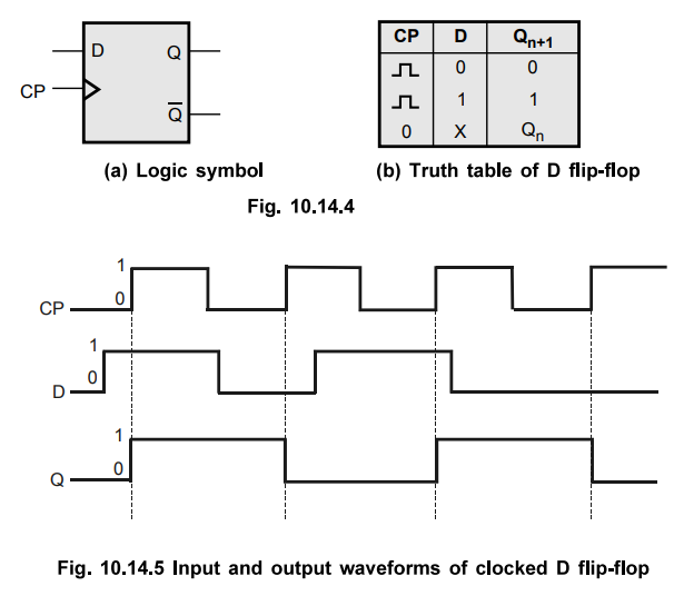
9. Structural Description of Pulse Triggered D Flip-Flop
Like
in D-latch, in D flip-flop the basic SR flip-flop is used with complemented
inputs. The D flip-flop is similar to D-latch
except clock pulse is usedinstead of enable input. Fig. 10.14.4 shows logic
symbol and truth table for D flip-flop and Fig. 10.14.5 shows the input and
output waveforms.
Listing
10.14.2 : VHDL description of a D flip-flop,
library
ieee;
use
ieee.std_logic_1164.all;
entity
D_FF is
port
( D, CP : in std_logic;
Q,
Qbar : buffer std_logic);
end
D_FF;
architecture
FF of D_FF is
-
Here Q and Qbar signals are declared as buffer; however these signals are
-
mapped with in and out signals. Some simulators may not allow such
-
mapping. In this case, change all in and out to buffer,
component
nand2
port
( I1, I2 : in std_logic;
O1
: out std_logic);
end
component;
for
all: nand2 use entity work.two_input (nand2_7);
signal
SI, R, Rl : std_logic;
begin
NA1
: nand2 port map (D, CP, SI);
NA2
: nand2 port map (R, CP, Rl);
NA3
: nand2 port map (D, D, R); — nand gate used as an inverter
NA4
: nand2 port map (SI, Qbar, Q);
NA5
: nand2 port map (Q, Rl, Qbar);
end
FF;
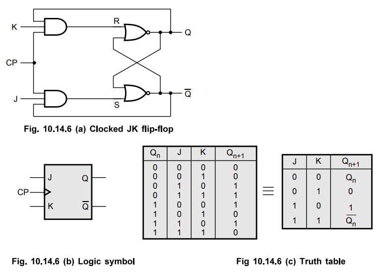
10. Structural Description of JK Flip-Flop
•
The Fig. 10.14.6 (a) shows the pulse triggered JK flip-flop, and Fig. 10.14.6
(b) and (c) shows the logic symbol and truth table for JK flip-flop.
Listing 10.14.3 VHDL description of JK flip-flop.
library
ieee;
use
ieee.std_logic_1164.all;
entity
JK_FF is
port
(J, K, CP: in std_logic;
Q,
Qbar: buffer std_logic);
--Q,
Qbar are declared buffer because they behave as input and output.
end
JK_FF;
architecture
FF of JK_FF is
--
Here Q and Qbar signals are declared as buffer; however these signals are
--
mapped with in and out signals. Some simulators may not allow such
mapping. In this case, change all in and out to buffer,
component
nor2
port
( II, 12 : in std_logic;
O1
: out std_logic);
end
component;
component
and3
port
( II, 12, 13 : in std_logic;
O1
: out std_logic);
end
component;
for
all : nor2 use entity work.two_input (nor2_7);
for
all: and3 use entity work.three_input (and3_7);
signal
R, S
begin
N1
: nor2 port map (S, Q, Qbar);
N2
: nor2 port map (R, Qbar, Q);
A1
: and3 port map (Q, K, CP, R);
A2
: and3 port map (Qbar, J, CP, S);
end
FF;
11. Behavioral Description of JK Flip-Flop using Case Statement
Listing
10.14.4 : VHDL code for a positive edge-triggered JK flip-flop using the case
statement,
library
ieee;
use
ieee.std_logic_1164.all;
entity
JKFF is
port(JK
: in bit_vector (1 downto 0);
clk
: in std_logic;
Q,
Qbar : out bit);
end
JK_FF;
architecture
Flip_Flop of JK_FF is
begin
P1
: process (elk)
variable
tempi, temp2 : bit;
begin
if
rising_edge (elk) then
case
JK is
when
"01" => tempi := 'O';
when
"10" => tempi := '1';
when
"00" => tempi := tempi;
when
"11" => tempi := not tempi;
end
case;
Q
< = temp1;
temp2
:= not temp1;
Qbar
< = temp2;
end
if;
end
process P1;
end
Flip_Flop;
12. Description of D Flip-Flop using VHDL Function
•
The listing 10.14.5 shows the VHDL description of positive edge trigger D
flip-flop. The positive edge detection is accomplished by the use of S'event
and S'last value signal attributes. The S'event attribute indicates any
occurrence of the event and S'last_value gives the previous value of S. Thus if
previous value is 0 and S'event is true then there is a rising edge or positive
edge.
Listing
10.14.5 : VHDL function to describe the edge trigger D flip-flop.
library
ieee;
use
ieee.std_logic_1164.all;
entity
DFF is
port
( D, elk : in std_logic;
Q
: out stdlogic);
end
DFF
architecture
Dflip_flop of DFF is
function
rising_edge (signal s : std_logic) - function declaration
return
boolean is - function declaration
begin
if
(s'event) and (s = '1') and – s’event and s’last_value are signal attributes
(s'last_value
= '0') then - s’event returns true if an event occurred during
return
true; - current delta; otherwise it
returns false
else
– s’last value return the previous value of s
return
false; - before the last event, Thus, rising edge is
end
if; - detected if (s’event) and (s=’1’) and
end
rising_edge; = (s’last_vale = ‘0’) results true.
begin
process(
clk)
begin
if
rising_edge(clk) then
Q
< = D;
end
if;
end
process;
end
Dflip_flop;
Review Questions
1. Give the VHDL description for D, JK and T flip-flops.
2. Construct a VHDL module for a ]K flipflop.
3. Write the behavioral modeling code for a D flip flop.
Digital Logic Circuits: Unit V: VHDL : Tag: : - VHDL Description of Flip-Flops
Related Topics
Related Subjects

Digital Logic Circuits
EE3302 3rd Semester EEE Dept | 2021 Regulation | 3rd Semester EEE Dept 2021 Regulation