Electron Devices and Circuits: Unit V: (b) Oscillators
Wlen Bridge Oscillator
Derivation of Frequency, Advantages, Disadvantages, Comparison, Solved Example Problems
• The Wien bridge oscillator is also an RC oscillator which uses Wien bridge circuit as its feedback network.
Wlen Bridge Oscillator
•
The Wien bridge oscillator is also an RC oscillator which uses Wien bridge
circuit as its feedback network.
•
The amplifier used in this oscillator is a noninverting amplifier which does
not introduce any phase shift.
•
The feedback network which is a Wien bridge circuit also does not introduce any
phase shift.
•
Thus phase shift around a loop in a Wien bridge oscillator is 0°.
•
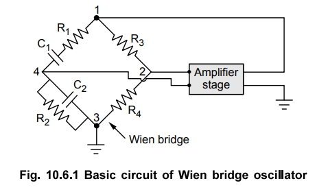
The Fig. 10.6.1 shows the basic circuit of Wien bridge oscillator.
•
The output of the amplifier is applied between terminals 1 and 3 while
amplifier is supplied from terminals 2 and 4 which is the output of the
feedback network.
1. Derivation of Frequency
•
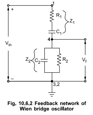
The Fig. 10.6.2 shows the feedback network of Wien bridge oscillator.
•
The two arms which are Rx, C| m series and R2, C2 in parallel are frequency
sensitive arms and hence only those arms are considered in the Fig. 10.6.2.
•
Input to feedback network is Vin applied between 1 and 3, which is amplifier
output.
•
Output of feedback network is Vf taken from 2 and 4.
•
This network is also called lead-lag network.
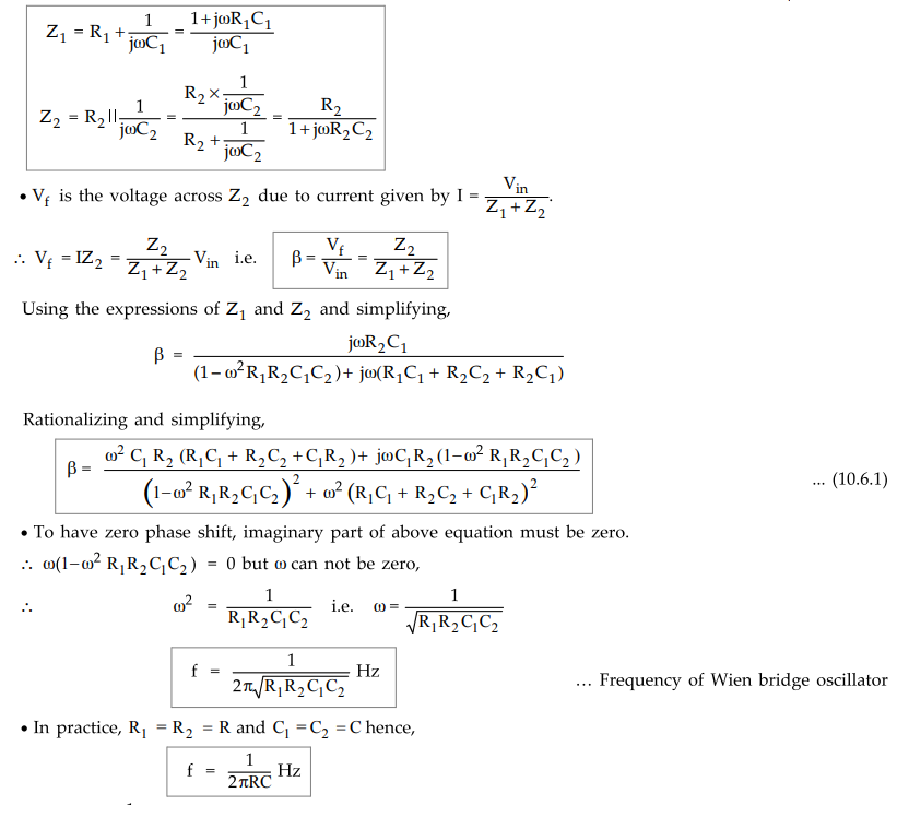
Using
ω = 1/ RC in the equation (10.6.1) we get the magnitude of the feedback network
as,
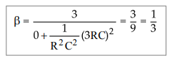 •
As |Aβ| ≥ 1 hence |A| ≥ 3 for Wien
bridge oscillator.
•
As |Aβ| ≥ 1 hence |A| ≥ 3 for Wien
bridge oscillator.
•
Thus the gain of amplifier stage must be at least 3 to ensure sustained
oscillations in Wien bridge oscillator.
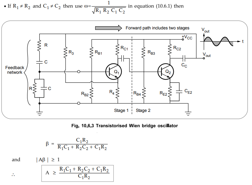
2. Wien Bridge Oscillator using Transistor
•
The Fig. 10.6.3 shows Wien bridge oscillator using transistor. It uses two
stage common emitter amplifier. Each stage contributes 180° phase shift hence
total phase shift due to amplifier stage is 360° i.e. 0°. The Wien bridge
consists of R and C in series, R and C in parallel as its frequency sensitive
arms and R3 and R4 as remaining two sides. The input to
feedback is applied from collector of Q2 through coupling capacitor.
•
Both the capacitors are ganged so that they can be varied simultaneously to
vary the frequency. The resistance R4 serves two purposes. It is
part of Wien bridge and also unbypassed emitter resistance of Q1.
The two stage amplifier provides gain much more than 3, which may distort the
output. Thus the gain is controlled by providing negative feedback without
bypassing resistance R4 in the first stage of amplifier. This is called
amplitude stabilization. The amplitude stability can be further improved using
nonlinear resistance R4. Due to this, loop gain depends on the
amplitude of oscillations.
•
As the amplitude increases, the resistance R4 decreases and the current through
it increases. This increases the negative feedback and reduces the gain. This
controls the amplitude of the oscillations and avoids the output waveform
distortion.
•
The expression for the frequency of oscillations is,
f
= (1 / 2πRC) Hz
3. Advantages and Disadvantages
•
The advantages of Wien bridge oscillator are,
1.
Mounting the two capacitors on common shaft and varying their values, the
frequency can be varied as per the requirement.
2.
Due to the use of two stage amplifier, the gain is high.
3.
The stability is high.
4.
It provides stable low distortion sinusoidal output.
5.
The frequency range can be selected simply by using decade resistance boxes.
6.
The circuit is easy from design point of view and gives constant output.
•
The disadvantages of Wien bridge oscillator are,
1.
It cannot be used to generate high frequencies.
2.
The circuit needs two transistors and a large number of other components.
3.
The maximum frequency is limited due to the amplitude and the phase shift
characteristics of the amplifiers.
Ex.
10.6.1 The frequency sensitive arms of the Wien bridge oscillator uses C1
= C2 = 0.001 pF and R2 = 10 kΩ while R2 is
kept variable. The frequency is to be varied from 10 kHz to 50 kHz, by varying
R2. Find the minimum and maximum values of R2
Sol.
:
The frequency of the oscillator is given by,
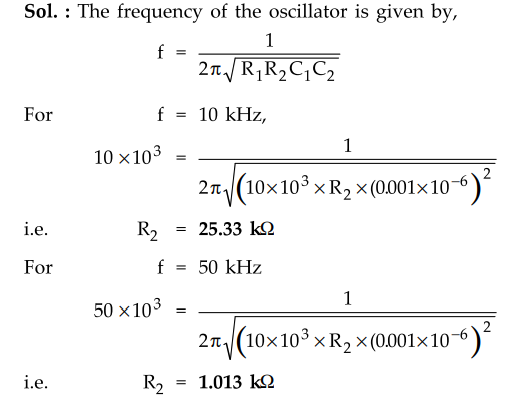
So
minimum value of R2 is i.013 kΩ while the maximum value of R2 is
25.33 kΩ
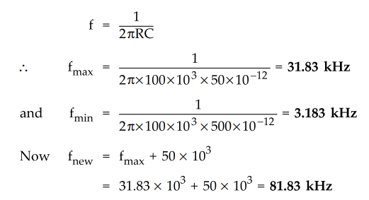
Ex.
10.6.2 In a Wien bridge oscillator R1 = R2 = 100 k and the ganged variable
capacitor has a range from 50 pF to 500 pF. Find the range of the frequency of
the oscillations possible.
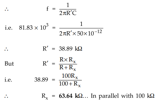
If
the frequency desired is 50 kHz more than the maximum frequency calculated
above, find the value of the resistance to be connected in parallel with 100 k
Ω.
Sol.
:
For a Wien bridge oscillator,
The
corresponding R = R' with an additional resistance Rx in parallel.
Ex. 10.6.3 Design a Wien bridge oscillator circuit to oscillate at a frequency of 20 kHz.
Sol.
: f = 20 kHz
For
a Wien bridge oscillator with R1 = R2 = R and C1
= C2
•
The designed circuit is as shown in the Fig. 10.6.3.
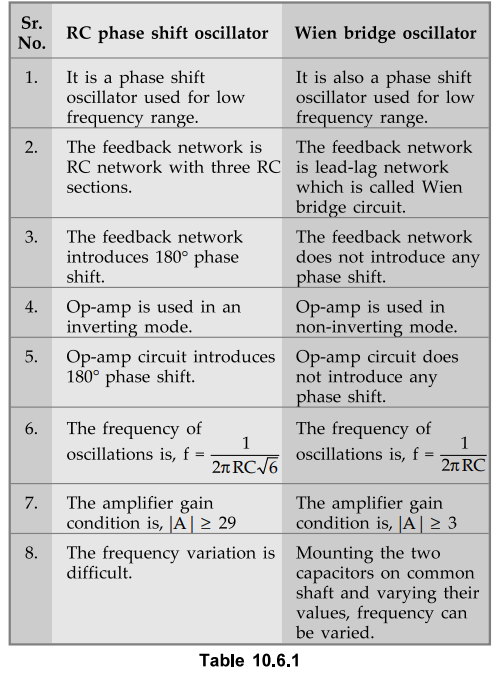
4. Comparison of RC Phase Shift and Wien Bridge Oscillators
1. Explain the principle of operation of a Wien bridge
oscillator.
2. What are the advantages and disadvantages of Wien bridge
oscillator?
3. Draw the circuit of a Wien bridge oscillator. Derive the
transfer function P fro) of the phase lead-lag network used and hence explain
how Barkhausen conditions are satisfied in this RC oscillator.
Electron Devices and Circuits: Unit V: (b) Oscillators : Tag: : Derivation of Frequency, Advantages, Disadvantages, Comparison, Solved Example Problems - Wlen Bridge Oscillator
Related Topics
Related Subjects

Electron Devices and Circuits
EC3301 3rd Semester EEE Dept | 2021 Regulation | 3rd Semester EEE Dept 2021 Regulation