Electric Circuit Analysis: Unit I: b. Basic circuits analysis
Worked examples: AC circuit
Electric Circuit Analysis: Unit I: Basic circuits analysis : Worked examples
WORKED EXAMPLES
Example
4 A voltage v = 100 sin 100 nt is applied to a circuit consisting of a pure
resistor of 20 Ω Find the following quantities.
(a)
Maximum voltage
(b)
Frequency of supply
(c)
The expression for the instantaneous current
Solution:
Data:
v
= 100 sin 100 πt … (i)
R
= 20 Ω
The
standard form of sinusoidal voltage is given by v = Vm sin ot
Comparing
equations (i) and (ii)
Vm
= 100 volts
ω
= 100 π
⇒ 2 π f = 100 π
⇒ f 100π / 2π = 50 Hz
The
expression for the instantaneous current is
i = v / R
=
100 / 20 sin 100πt
i
= 5 sin 100лt
Example
5 An inductive coil has negligible resistance and inductance of 0.1 henry. It
is connected across a 220 V, 50 Hz supply. Find the current and power. Also
write down the expressions for instantaneous applied voltage and current.
Solution:
Data:
L
= 0.1 H
V
= VRMS = 220 V
f
= 50 Hz
Required:
(a) I, (b) W, (c) v, (d) i

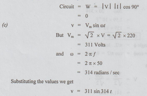
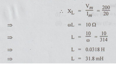
(b) The average power consumed by inductive
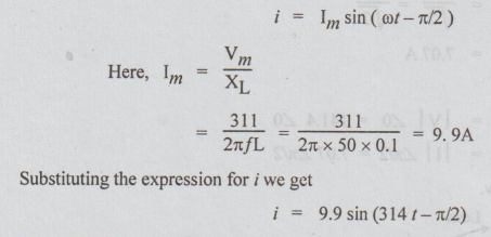
(d) For purely inductive circuit, when V is
taken as reference, i is given by
Example
6 In an A.C circuit, the applied voltage is given by v = 200 sin 314t and the
expression for the leading current is given by i = 10 cos 314 t. Find the
circuit constant and find the power factor of the circuit. Draw the phasor
diagram.
Solution:
Data:
V
= 200 sin 314t ... (i)
i
= 10 cos 314 t ... (ii)
Both
equations must be either in the sine form or cosine form.
The
equation for i can be written as i = 10 sin (π/2 + 314 t)
=
10 sin (314t + π/2) … (iii)
Comparing
equations (i) and (iii) we can say that I leads V by л/2.
i.e.,
the circuit element is purely capacitive.
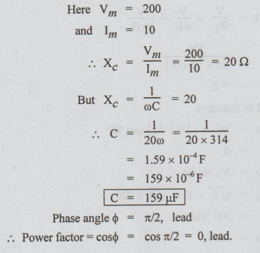
Here
Vm = 200
and
Im = 10
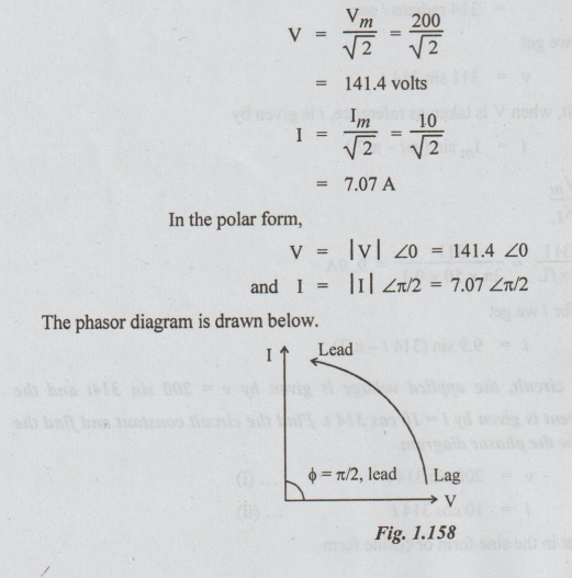
To
draw phasor diagram
Example
7 In a circuit, the source voltage is
V
= 200 sin (314t+π/6) and
the
current is i = 20 sin (314t – π/3)
Find
the following.
(a) The frequency
(b)
Maximum values of voltage and current
(c)
RMS values of voltage and current
(d) Average value of both voltage and current
(e)
Voltage and current in polar form
(f)
Draw phasor diagram
(g)
Circuit element and its value.
Solution:
Data:

(g) Refer the phasor diagram. The current
seems to be lagging behind the voltage by an angle = (30+ 60=90°). It is
possible only when the circuit element is purely inductance.
Let
the inductive reactance be XL
Example
8 A voltage e = 250 sin at when applied to a resistor is found to give a power
of 100 watts. Find the value of resistor and write the equation for current.
State whether the value of resistor varies when the frequency is changed.
Solution:
Data:
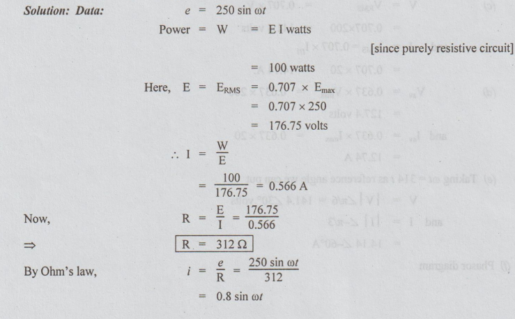
The
resistance is independent of frequency i.e. the variation of frequency will not
affect the resistance of the resistor
Example
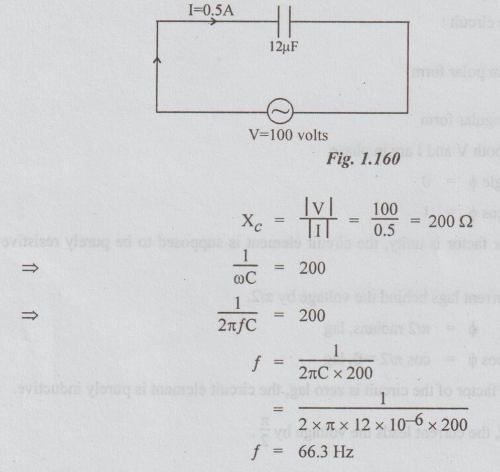
9 A voltage of 100 volts is applied to a capacitor of 12uF. The current is
0.5A. What must be the frequency of supply?
Solution:
Data: The given voltage and current are considered to be
r.m.s. values.
i.e.,
V = 100 volts
I
= 0.5 A
C
= 12μF 12 × 10-6F
Electric Circuit Analysis: Unit I: b. Basic circuits analysis : Tag: : - Worked examples: AC circuit
Related Topics
Related Subjects

Electric Circuit Analysis
EE3251 2nd Semester 2021 Regulation | 2nd Semester EEE Dept 2021 Regulation