Physics for Electrical Engineering: Unit I: Dielectric Materials and Insulation
Dielectric Loss
Definition, Formula, Circuit, Waveform diagram, Factors affecting
When a dielectric is applied with AC voltage, the electrical energy is absorbed by the dielectric and certain quantity of electrical energy is dissipated in the form of heat energy.
DIELECTRIC
LOSS
When
a dielectric is applied with AC voltage, the electrical energy is absorbed by
the dielectric and certain quantity of electrical energy is dissipated in the
form of heat energy.
This
dissipation of electrical energy is known as dielectric loss.
Dielectric
loss can occur in both direct and alternating voltages. It is less in direct
voltage than that of alternating voltage.
Expression for dielectric loss (or
loss tangent)
When an AC voltage is applied to a perfect dielectric like vacuum or purified gas, it does not absorb electrical energy and there is no loss of electrical energy [fig. 1.12 (a)].
Polarisation
of the dielectric is in phase with the voltage. In such a case, the charging
current leads the applied voltage by an angle of 90° as shown in fig 1.12 (b).
We
know that power loss,
PL
= VI cos θ
When
θ = 90°, PL=V I cos90°
PL=
0
[
cos 90° = 0]
This
means that there is no power loss in the perfect dielectric.
However,
a practical dielectric has always some loss of electrical energy. In this case,
the leakage current does not lead the applied voltage exactly by 90°.
The
phase angle (θ) is always less than 90° as shown in fig. 1.12(c).
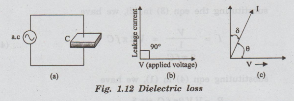
The
current leads the voltage by (90 – δ ). This shows that there is some loss in
electrical energy. δ is called dielectric loss angle. This loss angle is a
measure of the power dissipated in each cycle.
The
power loss in a dielectric having a capacitance C for applied voltage V of
frequency f is given by
PL=VI
cos θ
Since
θ = 90- δ, we have
PL
= VI cos (90° - δ) .... (1)
PL
= VI sin δ [cos(90° - δ) = sin δ]
We
know that V = IR or I = V / R
Similarly,
for capacitor if the capacitive reactance is Xe, we can write
I
= V / Xc... (2)
Further,
Xc depends on frequency of applied a.c voltage and capacitance. It
is given by
Xc
= 1 / 2 л f С ...(3)
substituting
the eqn (3) in (2), we have
substituting
eqn (4) in (1), we have
PL=VV
2π fC sin δ
РL
= 2π f C V2 sin δ
In
most of the dielectrics, the angle δ is very small.
sin
δ = tan δ
Dielectric
power loss PL = 2n fC V2tan δ ... (6)
It
is noted that the power loss depends on tan 8 as long as other factors like
voltage, frequency and capacitance are constant.
tan δ is called the power factor of the dielectric.
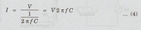
Variation of power loss with
frequency
The
power loss changes with frequency. Its value is high in the electrical
frequency and low in the optical frequency (fig. 1.13).
Factors affecting dielectric loss
Dielectric
loss may increase due to the following factors.
•
high frequency of the applied voltage
•
high value of the applied voltage
•
presence of humidity
•
temperature rise
Note: Dielectric loss is an engineering problem involving heat
generation and heat dissipation. It plays a dominant role in high voltage
applications.
Physics for Electrical Engineering: Unit I: Dielectric Materials and Insulation : Tag: : Definition, Formula, Circuit, Waveform diagram, Factors affecting - Dielectric Loss
Related Topics
Related Subjects

Physics for Electrical Engineering
PH3202 2nd Semester 2021 Regulation | 2nd Semester EEE Dept 2021 Regulation