Transmission and Distribution: Unit V: (b) Substations and Grounding
Earthed Neutral System
Solid Grounding - Resistance Earthing - Reactance Earthing - Resonant Grounding - Voltage Transformer Earthing Earthing Transformers
Questions : 1. What are advantages of neutral earthing? 2. What do you mean by effectively grounded and noneffectively grounded systems? 3. Explain solid grounding?4. What is the drawback of reactance grounding ? 5. Write a short note on resonant grounding.
Earthed Neutral System
AU : May-08,10,13,15, 16,18, Dec.-15,
16, 17
In this system, the neutral is earthed
either directly or through resistance or reactance depending on the
requirement. Thus the system neutral can be grounded effectively or
non-effectively. In effectively grounded system, the neutral is grounded
directly and hence it is called solid grounding. Following methods are adopted
for non-effectively grounded systems.
i) Resistance earthing
ii) Reactance earthing
iii) Arc supression coil or resonant
earthing
iv) Voltage transformer earthing
v) Earthing transformer
The advantages of neutral earthing are
as follows,
i) The arcing grounds are prevented from
occuring by employing suitable switchgears.
ii) As the neutral point is not shifted
in this system, thus the voltages of healthy phases remains nearly constant.
iii) The static charges which are
induced are grounded immediately and are thus prevented from causing any
disturbance.
iv) The faulty part of the system can be
isolated from the remaining system with the help of earth fault relays.
v) The magnitude of transient voltage is
small in this system.
vi) The discriminative type fault
indicator can be installed on such systems.
vii) This system is more reliable,
provides safety to personnel and equipment with reduced operational and
maintenance cost than ungrounded system.
1. Solid Grounding
AU : May-10, 13
In this method of earthing, neutral is
directly connected to earth by a metallic connection or a wire of negligible
resistance and reactance. The charging currents flow through the system under
normal condition similar to ungrounded system.
Because of the connection of system
neutral point to earth, it always remains at earth potential at all operating
conditions and under faulty conditions voltage of healthy phase will not
exceed.
The solid grounding is represented in
the Fig. 8.13.1.
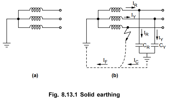
Whenever there is earth fault on any one
phase (phase B in this case), the phase to earth voltage of faulty phase is
zero while voltage to earth of the remaining two healthy phases will be normal
phase voltages as neutral in this case is not shifted. The phasor diagram corresponding
to this condition is shown in the Fig. 8.13.2.
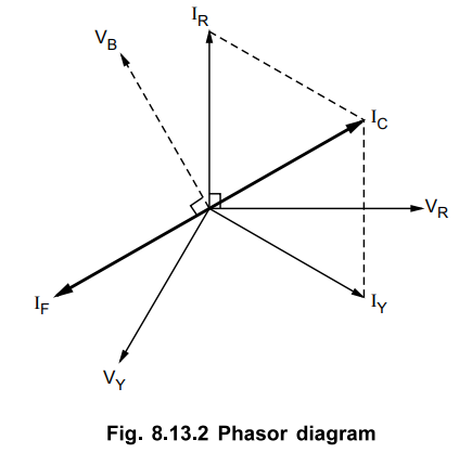
Let the capacitive currents flowing in
the healthy phases be IR and IY. the resultant capacitive
current is vector sum of IR and IY. The alternator in
addition to capacitive current also provides the fault current IF.
This current flows from fault point through faulty phase and then return to the
alternator through earth and neutral connection. The resistance of earth fault
is negligible. The magnitude of fault current after the analysis is given by,
IF = 3 Vph / Z1
+ Z2 + Z0
This current is mainly dependent on zero
sequence impedance of the source of power and that of phase conductor upto
fault point. As the resistive component of zero sequence impedance is normally
negligible, the fault current which is large can be assumed as lagging the
faulty phase voltage by 90°. From the phasor diagram it can be seen that IF and
Ic are exactly opposite due to which capacitive current is neutralised by high
fault current which eliminates the possibility of arcing grounds and
overvoltages. The discriminative types of switchgears may be used in this
method.
Following are disadvantages of
this method,
i) Due to high value of fault currents,
the system may become unstable and there will be greater interference to
neighbouring circuits. Thus this method is employed where system impedance is
sufficiently large to limit fault current.
ii) With high values of fault currents,
circuit breakers are difficult to handle and heavy contacts are to be provided
in the circuit breakers.
The above disadvantages can be overcome
by employing high rupturing capacity and high speed circuit breakers along with
fast operating relays.
This method is used in high voltage
systems with voltages below 33 kV with total capacity not exceeding 5000 kVA
for the economic reasons.
2. Resistance Earthing
In the cases where it is necessary to
limit the fault current then the current limiting element must be inserted in
the neutral and earth. One of the ways of achieving this is the use of
resistance earthing where one or more resistances are connected between neutral
and earth. The resistor may be either of wire or water column resistances for
voltages of 6.6 kV and above. Metallic resistors do not change with time and
requires little maintenance. But owing to its inductive nature they have
disadvantage with overhead lines exposed to lightning as impulses or the
travelling waves are subjected to positive reflection and cause stress on
insulation resulting in its breakdown. Liquid resistors are free from these
advantages and have simple and robust construction.
As shown in the Fig. 8.13.3 (a) let the
earth fault occurs on phase B. The corresponding phasor diagram is shown in the
Fig. 8.13.3 (b).
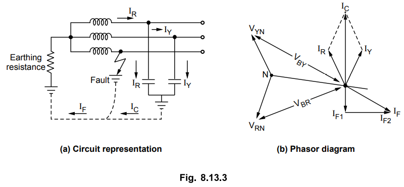
The capacitive currents IR and Iy flow
through the healthy lines. The fault current not only depends on the zero
sequence impedance of the source but also on the resistance in the earth
circuit. This fault current can be resolved into two components one inphase
with the faulty phase voltage and other lagging the faulty phase voltage by
90°. This lagging component of current is in phase opposition to capacitive
current and it changes with change in value of earthing resistance. Thus the
value of this resistance is designed in such a way that during fault on any
phase, a current equal to full load current of largest alternator or
transformer flows in earth resistance which will keep the overvoltages within
limits. With fault current lagging component equal to capacitive current the
system operation is similar to solidly earth system and no transients occur due
to arcing ground.
With high value of earthing resistance
and low value of reactive current than the capacitive current then system
conditions approach to that of ungrounded system with chances of transient over
voltages to occur. The line to earth voltage of the healthy phases at the time
of fault is little more than line to earth voltage of the solidly grounded
system operating under similar conditions. The duration of this voltage can be
reduced by using suitable protective switchgears to avoid any harmful effect
that may be caused.
The value of resistance to be inserted
in earth circuit is given by,
R = VL / √3.1
where
VL = Line to line voltage
I = Full load current of largest
alternator or transformer
The advantages of this system are as
follows,
1) The discriminative type of
switchgears may be used for protection.
2) The hazards due to arcing grounds are
minimized.
3) The influence on neighbouring
communication circuits is minimized due to lower value of fault current flowing
through earth as compared to that in case of solidly grounded system.
The disadvantages of this method are
given below,
1) As the neutral is shifted during
earth faults, the equipments are to be selected for greater voltages.
2) The system is expensive than the
solidly grounded system.
3) There is energy loss in neutral
grounding resistor for dissipation of fault energy.
This method is normally adopted in
systems with voltages from 2.2 kV and 33 kV with a power source capacity more
than 5000 kVA.
3. Reactance Earthing
In this system, instead of resistance, a
reactance is connected between neutral and earth with ratio of reactance to
resistance more than 3. The system is represented in the Fig. 8.13.4. Let the
earth fault occuring on phase B.
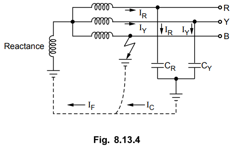
In addition to zero sequence impedance
of the source and faulty phase upto point of fault, the fault current is
dependent on fault current. By changing the value of reactance the fault
current can be varied. In practice this method is employed to give
characteristics similar to solidly earth system.
There is drawback of this system. With
increase in reactance, there is increase in transient voltages resulting from
arcing. Hence it is not commonly employed though it ensures satisfactory
relaying, partial grading of equipment insulation, less interference with
neighbouring circuits and intermediate cost.
For reactance earthing, it is necessary
that the magnitude of fault current should be at least 25 % of the three phase
fault current. This is higher than the requirement on resistance earthing and
thus it can be seen that the resistance earthing and the reactance earthing are
not similar.
4. Resonant Grounding
This system is also referred as arc
suppression coil grounding. In the previous earthing methods that we have
discussed the earth fault on any one of the phases causes total shut down of
the system. So continuity of supply can not be maintained. This is not the case
with ungrounded system where fault on one phase will not cause other phases to
supply power. This method of grounding has this advantage of isolated neutral
system along with reduced possibility of arcing grounds and numerous other
advantages.
It consists of a coil called Peterson
coil or Ground fault neutralizer or arc supression coil whose function is to
make arcing earth faults self extinguishing and in the case of sustained faults
to reduce the earth current to low value so that system can supply power with
one line earthed.
This system works on the principle that
when inductance and capacitance are connected in parallel, resonance takes
place between them and because of the characteristics of resonance, the fault
current is reduced or can be neutralized.
The system with fault on phase B is
shown in the Fig. 8.13.5 (a). The corresponding phasor diagram is shown in the
Fig. 8.13.5 (b).
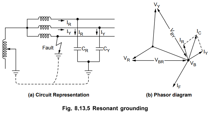
An arc supression coil is an iron-cored
reactor or similar to oil immersed transformer connected between neutral of
system and earth. This coil is provided with number of tappings so that it can
be tuned with the capacitance which may vary due to varying operational
conditions.
As the system operation is similar to
isolated neutral system, the phase to earth voltage of healthy phase is √3
times the normal phase voltage and the resultant capacitive current is 3 times
the normal charging current of one phase. The resultant capacitive current will
lead by 90° with faulty phase voltage while the fault current lags by 90° with
faulty phase voltage.
Now we have, IF = IC
at resonance
There is one problem with the above
method. As the operating conditions vary, the capacitance of the network also
vary. This can be overcome by using a tapped coil. The appropriate tapping is
required to be used for each of the change in the network conditions. The
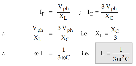
current rating of the coil is given by,
IF = 3Vph / XC
The time rating of coils used in systems
where earth faults are located and removed is around is around ten minutes. In
other systems continuous time rated coils are used.
The arc supression coil is shown in the
Fig. 8.13.6.
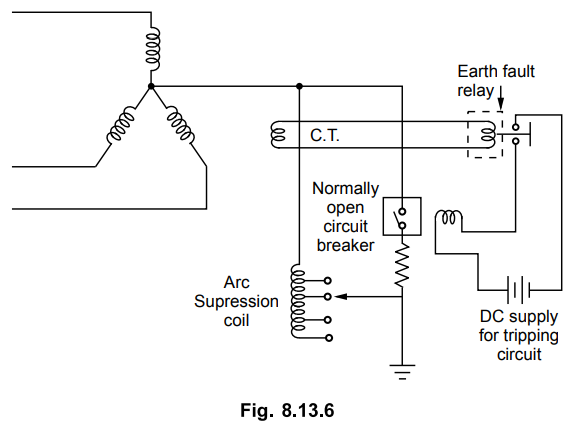
The coil is tapped in order to select
the reactance depending upon the length of transmission line and the
capacitance to be neutralized. The arc supression coil is connected between
neutral and ground.
The reactance of the coil can be
evaluated by using the expression L = 1 / 3 ω2C
The rating of the coil is continuous and
equal to the maximum earth fault current. If a double phase to ground fault or
another ground fault occurs, the current flowing through the coil is more. This
can be prohibited with closing of a circuit breaker after certain time lag. The
earth fault current flows through the parallel circuit by passing the arc
supression coil. Here the circuit breaker is normally open and closes after the
closure of relay tripping circuit by passing arc supression coil.
This method of neutral grounding is used
in medium voltage overhead transmission line which are connected to system
generators through intermediate power transformers. This is because the higher
insulation requirement on the apparatus associated with arc supression coil
grounding system is easily incorporated in power transformers than in
generators. Also the overhead lines are usually subjected to earth faults due
to lightning. Hence protection is required.
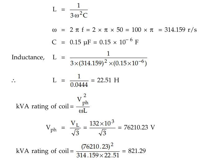
Example 8.13.1
Determine the inductance of Peterson coil to be connected between the
neutral and ground to neutralize the charging current of overhead line having
the line to ground capacitance of 0.15 pF. If the supply frequency is 50 Hz and
the operating voltage is 132 kV, Find the kVA rating of the coil.
Solution :
In case of Peterson coil we have,
Example 8.13.2
In a 50 Hz overhead line, the capacitance of one line to earth was 1.6 pF.
It was decided to use an earth fault neutralizer. Calculate the reactance to
neutralize the capacitance of i) 100 % of the length of line ii) 90 % of the
length of the line iii) 95 % of the length of the line.
Solution :
Inductive reactance, XL = ω L
= (314.159) (2.22) = 698.04 Ω
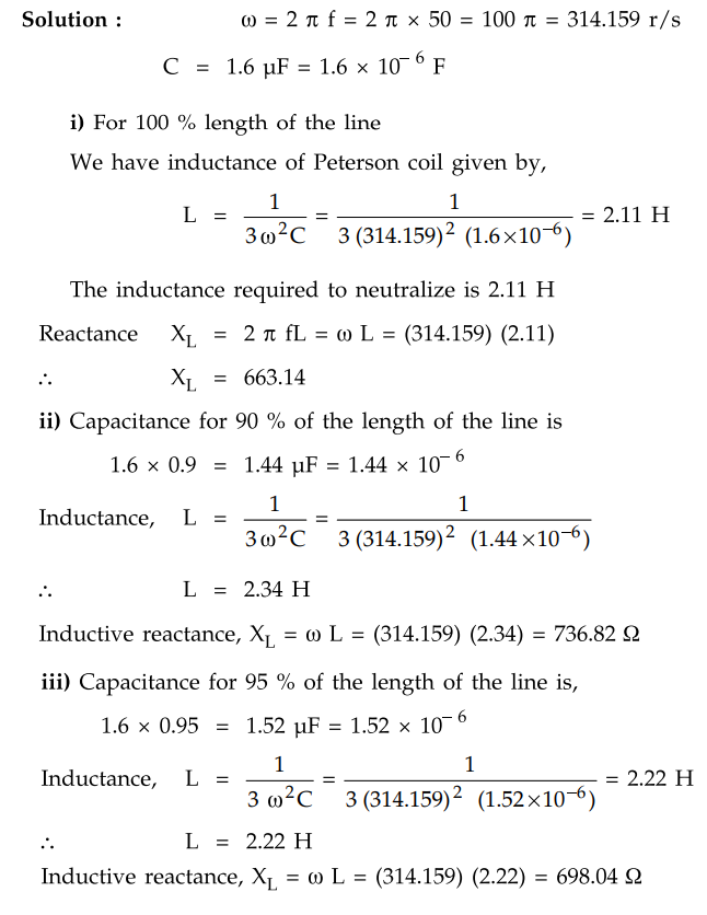
5. Voltage Transformer Earthing
In this system of earthing, the neutral
point is earthed through a single phase voltage transformer. The system thus
acts as an insulated neutral system. A very high reactance earthing is provided
due to the voltage transformer.
The connection diagram is shown in the
Fig. 8.13.7.
The voltage transformer shown in the
above figure measures the voltage so that earth fault on the system is
indicated. The travelling waves passing through the machine winding are
reflected through voltage transformer. A surge divertor is used between neutral
and earth to avoid the rise of voltage.
The voltage transformer is used normally
in generator circuits which are directly connected to step up transformers. The
generator circuits are physically isolated from the main distribution system.
The electrostatic capacity of the circuit is negligible as the interconnecting
cables between the generator and transformer windings are normally short. The risk
of overvoltage conditions arising due to arcing ground is eliminated.
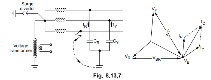
6. Earthing Transformers
When the transformers or generators are
delta connected or if the neutral points are not accessible then artificially
the neutral earthing point can be created with the use of star connected
earthing transformer. Such transformer has no secondary. Each phase of primary
has two equal parts. There are three limbs and each limb has two windings
providing opposite flux during normal condition. Such a transformer is shown in
the Fig. 8.13.8.
One set of windings are connected in
star providing the neutral point. The other ends of this set of windings are
connected to the second set of windings as shown in the Fig. 8.13.8. The
directions of the currents in the two windings on each limb are opposite to
each other. The small exciting current is circulated in the windings during
normal operation. Under faulty condition, the transformer offers a low
impedance path to the flow of zero phase sequence currents. The value of fault
current is limited in some cases by the use of a resistor in series with the
neutral earthing connection. This is necessary in systems with operating
voltage between 2.2 kV and 3.3 kV.
These transformers are of short time
ratings in the range of 10 seconds to 1 minute Hence the size of these
transformers is small as compared to power transformers of same rating. If the
earthing transformer is not available then a star-delta transformer is used.
Review Questions
1. What are advantages of neutral earthing?
2. What do you mean by effectively grounded and noneffectively
grounded systems?
3. What are various methods adopted for non-effectively grounded
systems?
4. Explain solid grounding?
5. What are disadvantages of solid grounding?
6. Explain resistance grounding?
7. State advantages of resistance grounding.
8. What are limitations of resistance grounding ?
9. Explain reactance grounding.
10. What is the drawback of reactance grounding ?
11. Write a short note on resonant grounding.
12. A 33 kV, 3 phase, 50 Hz overhead line 50 km long has a capacitance
earth line equal to 0.019 µF per km.
Determine the inductance and kVA rating of the arc supression coil.
[6.75 H, 169.3 kVA]
13. In a 50 Hz, overhead line, the capacitance of one line to earth
was 1.5 µF. It was decided to use an earth fault neutralizer. Calculate the
reactance to neutralize the capacitance of
i) 100 % of the length of the line ii) 90 % of the length of the
line iii) 95 % of the length of the line.
[i) 2.25 H ii) 2.5 H iii) 2.37 H]
14. Determine the value of reactance to be connected in the neutral
connection to neutralize the capacitance current of a overhead line to ground
capacitance of each line equal to 0.015 µF. The frequency is 50 Hz.
[22.6 H]
15. Derive the expression for the reactance of the Peterson coil.
16. Explain the working of arc supression coil.
17. Explain voltage transformer earthing.
18. Write short note on earthing transformer.
19. Explain the various methods of power system grounding in detail.
Transmission and Distribution: Unit V: (b) Substations and Grounding : Tag: : Solid Grounding - Resistance Earthing - Reactance Earthing - Resonant Grounding - Voltage Transformer Earthing Earthing Transformers - Earthed Neutral System
Related Topics
Related Subjects

Transmission and Distribution
EE3401 TD 4th Semester EEE Dept | 2021 Regulation | 4th Semester EEE Dept 2021 Regulation