Transmission and Distribution: Unit V: (b) Substations and Grounding
Grounding Grids
Question : 1. Write a note on grounding grids.
Grounding Grids
The low ground resistance in case of
high voltage substations can be obtained with the use of interconnected ground
grids. In a typical grounding grid system, a number of interconnected bare
solid copper conductors are buried at a depth of 0.3 to 0.6 m and spaced in a
grid pattern. It provides common earth for all devices and metallic structures
in the substation.
At each of the junction point, the
conductors are bonded together. This system is usually supported by a number of
vertical rods about 3 m long at some joints.
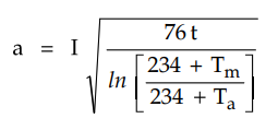
If a is cross-sectional area of copper,
in circular miles, t is the fault duration in seconds, Tm is the
maximum allowable temperature and Ta is the ambient temperature then
the size of grid conductors required which prevents fusing under the fault
current is given as,
If the grid depth is less than 0.25 m
then the earthing resistance of the grid is given by,
R = ρ / 4 √π/a + ρ / L
Here
R = Grid resistance in ohms
a = Ground area occupied by grid in m2
L = Total length of buried conductors in
m
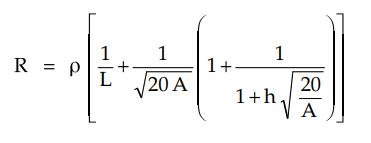
But when the grid depth is greater than
0.25 m then earthing resistance is given by,
The effective grounding of the equipment
is possible through the grid. Also the voltage gradiant at the surface of the
earth can be controlled at safe value for human contacts with the addition of
ground rods, the ground resistance further reduces when soil resistivity in the
upper layer is more than the soil underneath.
Review Question
1. Write a note on grounding grids.
Transmission and Distribution: Unit V: (b) Substations and Grounding : Tag: : - Grounding Grids
Related Topics
Related Subjects

Transmission and Distribution
EE3401 TD 4th Semester EEE Dept | 2021 Regulation | 4th Semester EEE Dept 2021 Regulation